Solution Lab 1 for MPLS Lab 005
Solution Lab:
MPLS
To understand why the ping is failing between two sides of the GRE tunnel you need to investigate the basic GRE troubleshooting reasons:
In this situation the IP addresses of the tunnel destination are not accessible from any CE router:
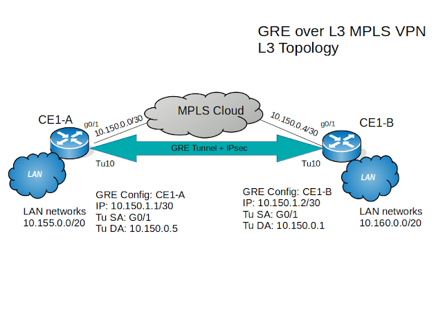
CE1-A#show running-config interface tunnel 10
Building configuration...
Current configuration : 130 bytes
!
interface Tunnel10
ip address 10.150.1.1 255.255.255.252
tunnel source GigabitEthernet0/1
tunnel destination 10.150.0.5
end
Ping the tunnel destination IP address:
CE1-A#ping 10.150.0.5
Type escape sequence to abort.
Sending 5, 100-byte ICMP Echos to 10.150.0.5, timeout is 2 seconds:
U.U.U
Success rate is 0 percent (0/5)
CE1-A#
The IP address is unreachable meaning that there is a problem with routing.
Check the routing table on the CE1-A router:
PE2# show ip route
S* 0.0.0.0/0 [1/0] via 10.150.0.2
10.0.0.0/8 is variably subnetted, 6 subnets, 3 masks
C 10.150.0.0/30 is directly connected, GigabitEthernet0/1
L 10.150.0.1/32 is directly connected, GigabitEthernet0/1
C 10.150.1.0/30 is directly connected, Tunnel10
L 10.150.1.1/32 is directly connected, Tunnel10
C 10.155.0.0/24 is directly connected, Loopback0
L 10.155.0.1/32 is directly connected, Loopback0
From the output above you can derive that the CE1-A router is using the default route when trying to reach 10.150.0.5 because of the “U”, one of the upstream routers is responding with ICMP unreachable messages. This leads to the two assumptions either the problem is on the opposite side of the GRE tunnel or somewhere in the ISP network.
To further verify the problem source you can you traceroute to the 10.150.0.5:
CE1-A#traceroute 10.150.0.5
Type escape sequence to abort.
Tracing the route to 10.150.0.5
VRF info: (vrf in name/id, vrf out name/id)
1 10.150.0.2 2 msec 2 msec 2 msec
2 10.150.0.2 !H * !H
CE1-A#
The very first hop is the node that sent the destination unreachable, meaning that the PE2 router is unable to access the CE2 router’s IP address.
Note: If you repeat troubleshooting steps above on the CE1-B router you will have identical results, only the responding router will be PE4.
Now, what is next? If you are the network engineer at the customer site then you need to contact the ISP’s staff, but since this the lab you need to access each of PE routers and see why they are unable to reach tunnel destination IP addresses.
To clarify this, we are talking about the PE2 router is unable to get to the IP address on the CE1-B router and the PE4 is unable to reach the IP address of the CE1-A router!
Next on the PE2 router lets see what is in the routing table of the CE1 VRF:
PE2#show ip route vrf CE1
Routing Table: CE1
10.0.0.0/8 is variably subnetted, 4 subnets, 3 masks
C 10.150.0.0/30 is directly connected, GigabitEthernet0/3
L 10.150.0.2/32 is directly connected, GigabitEthernet0/3
S 10.155.0.0/20 [1/0] via 10.150.0.1
B 10.160.0.0/20 [200/0] via 10.100.0.14, 03:04:22
PE2#
From the output, a conclusion can be made that the CE1 routing table is missing /30 subnet of the link between PE4 and CE1-B routers.
Also, check the CE1 routing table on the router PE4:
PE4#show ip route vrf CE1
Routing Table: CE1
10.0.0.0/8 is variably subnetted, 4 subnets, 3 masks
C 10.150.0.4/30 is directly connected, GigabitEthernet0/3
L 10.150.0.6/32 is directly connected, GigabitEthernet0/3
B 10.155.0.0/20 [200/0] via 10.100.0.12, 03:08:38
S 10.160.0.0/20 [1/0] via 10.150.0.5
The same is for PE4. It is missing the /30 subnet of the link between the PE2 and CE1-A routers.
Now that the problem has been identified, you need to check what is going on at the BGP VPNv4 tables:
Again first goes the router PE2:
PE2#show bgp vpnv4 unicast vrf CE1
BGP table version is 13, local router ID is 10.100.0.12
Network Next Hop Metric LocPrf Weight Path
Route Distinguisher: 1600:1600 (default for vrf CE1)
*> 10.155.0.0/20 10.150.0.1 0 32768 ?
*>i 10.160.0.0/20 10.100.0.14 0 100 0 ?
Next at the PE4:
PE4#show bgp vpnv4 unicast vrf CE1
BGP table version is 9, local router ID is 10.100.0.14
Network Next Hop Metric LocPrf Weight Path
Route Distinguisher: 1600:1600 (default for vrf CE1)
*>i 10.155.0.0/20 10.100.0.12 0 100 0 ?
*> 10.160.0.0/20 10.150.0.5 0 32768 ?
Both outputs demonstrate that 10.150.0.0/30 and 10.150.0.4/30 are not in the VPNv4 tables.
To confirm further the running-config for BGP should be checked:
PE2#show running-config | section bgp
router bgp 64500
bgp router-id 10.100.0.12
bgp log-neighbor-changes
neighbor 10.100.0.11 remote-as 64500
neighbor 10.100.0.11 update-source Loopback0
neighbor 10.100.0.13 remote-as 64500
neighbor 10.100.0.13 update-source Loopback0
neighbor 10.100.0.14 remote-as 64500
neighbor 10.100.0.14 update-source Loopback0
!
address-family vpnv4
neighbor 10.100.0.11 activate
neighbor 10.100.0.11 send-community both
neighbor 10.100.0.13 activate
neighbor 10.100.0.13 send-community extended
neighbor 10.100.0.14 activate
neighbor 10.100.0.14 send-community extended
exit-address-family
!
address-family ipv4 vrf CE1
redistribute static
exit-address-family
!
address-family ipv4 vrf PE2-PE1_T
redistribute connected
exit-address-family
!
address-family ipv4 vrf PE2-PE3_T
redistribute connected
exit-address-family
!
address-family ipv4 vrf PE2-PE4_T
redistribute connected
exit-address-family
PE4#show running-config | section bgp
router bgp 64500
bgp router-id 10.100.0.14
bgp log-neighbor-changes
neighbor 10.100.0.11 remote-as 64500
neighbor 10.100.0.11 update-source Loopback0
neighbor 10.100.0.12 remote-as 64500
neighbor 10.100.0.12 update-source Loopback0
neighbor 10.100.0.13 remote-as 64500
neighbor 10.100.0.13 update-source Loopback0
!
address-family vpnv4
neighbor 10.100.0.11 activate
neighbor 10.100.0.11 send-community extended
neighbor 10.100.0.12 activate
neighbor 10.100.0.12 send-community extended
neighbor 10.100.0.13 activate
neighbor 10.100.0.13 send-community extended
exit-address-family
!
address-family ipv4 vrf CE1
redistribute static
exit-address-family
!
address-family ipv4 vrf PE2-PE4_T
redistribute connected
exit-address-family
Address-family ipv4 vrf CE1 areas in the output are where proper configuration should be applied to fix the problem.
How to fix the issue:
Enter the bgp routing protocol global configuration mode on both PE2 and PE4 then under the address-family ipv4 vrf CE1 use the command “redistribute connected”
PE2(config)#router bgp 64500
PE2(config-router)#address-family ipv4 unicast vrf CE1
PE2(config-router-af)#redistribute connected
PE2(config-router-af)#exit
PE4(config)#router bgp 64500
PE4(config-router)#address-family ipv4 unicast vrf CE1
PE4(config-router-af)#redistribute connected
PE4(config-router-af)#exit
Verify again BGP VPNv4 and VRF CE1 Routing tables:
PE2#show bgp vpnv4 unicast vrf CE1
BGP table version is 16, local router ID is 10.100.0.12
Network Next Hop Metric LocPrf Weight Path
Route Distinguisher: 1600:1600 (default for vrf CE1)
*> 10.150.0.0/30 0.0.0.0 0 32768 ?
*>i 10.150.0.4/30 10.100.0.14 0 100 0 ?
*> 10.155.0.0/20 10.150.0.1 0 32768 ?
*>i 10.160.0.0/20 10.100.0.14 0 100 0 ?
PE2#show ip route vrf CE1
Routing Table: CE1
10.0.0.0/8 is variably subnetted, 5 subnets, 3 masks
C 10.150.0.0/30 is directly connected, GigabitEthernet0/3
L 10.150.0.2/32 is directly connected, GigabitEthernet0/3
B 10.150.0.4/30 [200/0] via 10.100.0.14, 00:03:52
S 10.155.0.0/20 [1/0] via 10.150.0.1
B 10.160.0.0/20 [200/0] via 10.100.0.14, 03:31:27
Back at the customer’s location, access the CE1-A and CE1-B routers, then check if tunnel destination IP addresses are accessible from each other:
CE1-A#ping 10.150.0.5
Type escape sequence to abort.
Sending 5, 100-byte ICMP Echos to 10.150.0.5, timeout is 2 seconds:
!!!!!
Success rate is 100 percent (5/5), round-trip min/avg/max = 4/5/8 ms
CE1-A#
CE1-B#ping 10.150.0.1
Type escape sequence to abort.
Sending 5, 100-byte ICMP Echos to 10.150.0.1, timeout is 2 seconds:
!!!!!
Success rate is 100 percent (5/5), round-trip min/avg/max = 4/5/7 ms
CE1-B#
Alright, now you see that the tunnel destination problem is solved.
Lastly, let's see if the GRE tunnel is working:
CE1-A#ping 10.150.1.2 source tunnel 10
Type escape sequence to abort.
Sending 5, 100-byte ICMP Echos to 10.150.1.2, timeout is 2 seconds:
Packet sent with a source address of 10.150.1.1
!!!!!
Success rate is 100 percent (5/5), round-trip min/avg/max = 6/6/8 ms
CE1-A#
Congratulations! You just completed the troubleshooting solution lab, save all configuration.
MPLS
Lab 005 Troubleshoot CE-to-CE connectivity problem

To understand why the ping is failing between two sides of the GRE tunnel you need to investigate the basic GRE troubleshooting reasons:
- Determine if IP addresses of the tunnel belong in the correct subnet ID.
- Verify if tunnel source and destination IP addresses are reachable from each of the CE routers.
- Check if ACL blocks GRE protocol or any related to GRE IP traffic.
In this situation the IP addresses of the tunnel destination are not accessible from any CE router:
CE1-A#show running-config interface tunnel 10
Building configuration...
Current configuration : 130 bytes
!
interface Tunnel10
ip address 10.150.1.1 255.255.255.252
tunnel source GigabitEthernet0/1
tunnel destination 10.150.0.5
end
Ping the tunnel destination IP address:
CE1-A#ping 10.150.0.5
Type escape sequence to abort.
Sending 5, 100-byte ICMP Echos to 10.150.0.5, timeout is 2 seconds:
U.U.U
Success rate is 0 percent (0/5)
CE1-A#
The IP address is unreachable meaning that there is a problem with routing.
Check the routing table on the CE1-A router:
PE2# show ip route
S* 0.0.0.0/0 [1/0] via 10.150.0.2
10.0.0.0/8 is variably subnetted, 6 subnets, 3 masks
C 10.150.0.0/30 is directly connected, GigabitEthernet0/1
L 10.150.0.1/32 is directly connected, GigabitEthernet0/1
C 10.150.1.0/30 is directly connected, Tunnel10
L 10.150.1.1/32 is directly connected, Tunnel10
C 10.155.0.0/24 is directly connected, Loopback0
L 10.155.0.1/32 is directly connected, Loopback0
From the output above you can derive that the CE1-A router is using the default route when trying to reach 10.150.0.5 because of the “U”, one of the upstream routers is responding with ICMP unreachable messages. This leads to the two assumptions either the problem is on the opposite side of the GRE tunnel or somewhere in the ISP network.
To further verify the problem source you can you traceroute to the 10.150.0.5:
CE1-A#traceroute 10.150.0.5
Type escape sequence to abort.
Tracing the route to 10.150.0.5
VRF info: (vrf in name/id, vrf out name/id)
1 10.150.0.2 2 msec 2 msec 2 msec
2 10.150.0.2 !H * !H
CE1-A#
The very first hop is the node that sent the destination unreachable, meaning that the PE2 router is unable to access the CE2 router’s IP address.
Note: If you repeat troubleshooting steps above on the CE1-B router you will have identical results, only the responding router will be PE4.
Now, what is next? If you are the network engineer at the customer site then you need to contact the ISP’s staff, but since this the lab you need to access each of PE routers and see why they are unable to reach tunnel destination IP addresses.
To clarify this, we are talking about the PE2 router is unable to get to the IP address on the CE1-B router and the PE4 is unable to reach the IP address of the CE1-A router!
Next on the PE2 router lets see what is in the routing table of the CE1 VRF:
PE2#show ip route vrf CE1
Routing Table: CE1
10.0.0.0/8 is variably subnetted, 4 subnets, 3 masks
C 10.150.0.0/30 is directly connected, GigabitEthernet0/3
L 10.150.0.2/32 is directly connected, GigabitEthernet0/3
S 10.155.0.0/20 [1/0] via 10.150.0.1
B 10.160.0.0/20 [200/0] via 10.100.0.14, 03:04:22
PE2#
From the output, a conclusion can be made that the CE1 routing table is missing /30 subnet of the link between PE4 and CE1-B routers.
Also, check the CE1 routing table on the router PE4:
PE4#show ip route vrf CE1
Routing Table: CE1
10.0.0.0/8 is variably subnetted, 4 subnets, 3 masks
C 10.150.0.4/30 is directly connected, GigabitEthernet0/3
L 10.150.0.6/32 is directly connected, GigabitEthernet0/3
B 10.155.0.0/20 [200/0] via 10.100.0.12, 03:08:38
S 10.160.0.0/20 [1/0] via 10.150.0.5
The same is for PE4. It is missing the /30 subnet of the link between the PE2 and CE1-A routers.
Now that the problem has been identified, you need to check what is going on at the BGP VPNv4 tables:
Again first goes the router PE2:
PE2#show bgp vpnv4 unicast vrf CE1
BGP table version is 13, local router ID is 10.100.0.12
Network Next Hop Metric LocPrf Weight Path
Route Distinguisher: 1600:1600 (default for vrf CE1)
*> 10.155.0.0/20 10.150.0.1 0 32768 ?
*>i 10.160.0.0/20 10.100.0.14 0 100 0 ?
Next at the PE4:
PE4#show bgp vpnv4 unicast vrf CE1
BGP table version is 9, local router ID is 10.100.0.14
Network Next Hop Metric LocPrf Weight Path
Route Distinguisher: 1600:1600 (default for vrf CE1)
*>i 10.155.0.0/20 10.100.0.12 0 100 0 ?
*> 10.160.0.0/20 10.150.0.5 0 32768 ?
Both outputs demonstrate that 10.150.0.0/30 and 10.150.0.4/30 are not in the VPNv4 tables.
To confirm further the running-config for BGP should be checked:
PE2#show running-config | section bgp
router bgp 64500
bgp router-id 10.100.0.12
bgp log-neighbor-changes
neighbor 10.100.0.11 remote-as 64500
neighbor 10.100.0.11 update-source Loopback0
neighbor 10.100.0.13 remote-as 64500
neighbor 10.100.0.13 update-source Loopback0
neighbor 10.100.0.14 remote-as 64500
neighbor 10.100.0.14 update-source Loopback0
!
address-family vpnv4
neighbor 10.100.0.11 activate
neighbor 10.100.0.11 send-community both
neighbor 10.100.0.13 activate
neighbor 10.100.0.13 send-community extended
neighbor 10.100.0.14 activate
neighbor 10.100.0.14 send-community extended
exit-address-family
!
address-family ipv4 vrf CE1
redistribute static
exit-address-family
!
address-family ipv4 vrf PE2-PE1_T
redistribute connected
exit-address-family
!
address-family ipv4 vrf PE2-PE3_T
redistribute connected
exit-address-family
!
address-family ipv4 vrf PE2-PE4_T
redistribute connected
exit-address-family
PE4#show running-config | section bgp
router bgp 64500
bgp router-id 10.100.0.14
bgp log-neighbor-changes
neighbor 10.100.0.11 remote-as 64500
neighbor 10.100.0.11 update-source Loopback0
neighbor 10.100.0.12 remote-as 64500
neighbor 10.100.0.12 update-source Loopback0
neighbor 10.100.0.13 remote-as 64500
neighbor 10.100.0.13 update-source Loopback0
!
address-family vpnv4
neighbor 10.100.0.11 activate
neighbor 10.100.0.11 send-community extended
neighbor 10.100.0.12 activate
neighbor 10.100.0.12 send-community extended
neighbor 10.100.0.13 activate
neighbor 10.100.0.13 send-community extended
exit-address-family
!
address-family ipv4 vrf CE1
redistribute static
exit-address-family
!
address-family ipv4 vrf PE2-PE4_T
redistribute connected
exit-address-family
Address-family ipv4 vrf CE1 areas in the output are where proper configuration should be applied to fix the problem.
How to fix the issue:
Enter the bgp routing protocol global configuration mode on both PE2 and PE4 then under the address-family ipv4 vrf CE1 use the command “redistribute connected”
PE2(config)#router bgp 64500
PE2(config-router)#address-family ipv4 unicast vrf CE1
PE2(config-router-af)#redistribute connected
PE2(config-router-af)#exit
PE4(config)#router bgp 64500
PE4(config-router)#address-family ipv4 unicast vrf CE1
PE4(config-router-af)#redistribute connected
PE4(config-router-af)#exit
Verify again BGP VPNv4 and VRF CE1 Routing tables:
PE2#show bgp vpnv4 unicast vrf CE1
BGP table version is 16, local router ID is 10.100.0.12
Network Next Hop Metric LocPrf Weight Path
Route Distinguisher: 1600:1600 (default for vrf CE1)
*> 10.150.0.0/30 0.0.0.0 0 32768 ?
*>i 10.150.0.4/30 10.100.0.14 0 100 0 ?
*> 10.155.0.0/20 10.150.0.1 0 32768 ?
*>i 10.160.0.0/20 10.100.0.14 0 100 0 ?
PE2#show ip route vrf CE1
Routing Table: CE1
10.0.0.0/8 is variably subnetted, 5 subnets, 3 masks
C 10.150.0.0/30 is directly connected, GigabitEthernet0/3
L 10.150.0.2/32 is directly connected, GigabitEthernet0/3
B 10.150.0.4/30 [200/0] via 10.100.0.14, 00:03:52
S 10.155.0.0/20 [1/0] via 10.150.0.1
B 10.160.0.0/20 [200/0] via 10.100.0.14, 03:31:27
Back at the customer’s location, access the CE1-A and CE1-B routers, then check if tunnel destination IP addresses are accessible from each other:
CE1-A#ping 10.150.0.5
Type escape sequence to abort.
Sending 5, 100-byte ICMP Echos to 10.150.0.5, timeout is 2 seconds:
!!!!!
Success rate is 100 percent (5/5), round-trip min/avg/max = 4/5/8 ms
CE1-A#
CE1-B#ping 10.150.0.1
Type escape sequence to abort.
Sending 5, 100-byte ICMP Echos to 10.150.0.1, timeout is 2 seconds:
!!!!!
Success rate is 100 percent (5/5), round-trip min/avg/max = 4/5/7 ms
CE1-B#
Alright, now you see that the tunnel destination problem is solved.
Lastly, let's see if the GRE tunnel is working:
CE1-A#ping 10.150.1.2 source tunnel 10
Type escape sequence to abort.
Sending 5, 100-byte ICMP Echos to 10.150.1.2, timeout is 2 seconds:
Packet sent with a source address of 10.150.1.1
!!!!!
Success rate is 100 percent (5/5), round-trip min/avg/max = 6/6/8 ms
CE1-A#
Congratulations! You just completed the troubleshooting solution lab, save all configuration.

Comments
Post a Comment