MPLS Lab 004 CE-PE Routing Using Redistribute Static
Image requirements:
VIRL: IOSv 15.7
EVE-NG: Cisco vIOS Router vios-15.6
GNS3: vios-adventerprisek9-m.vmdk.SPA.156-2.T
Description:
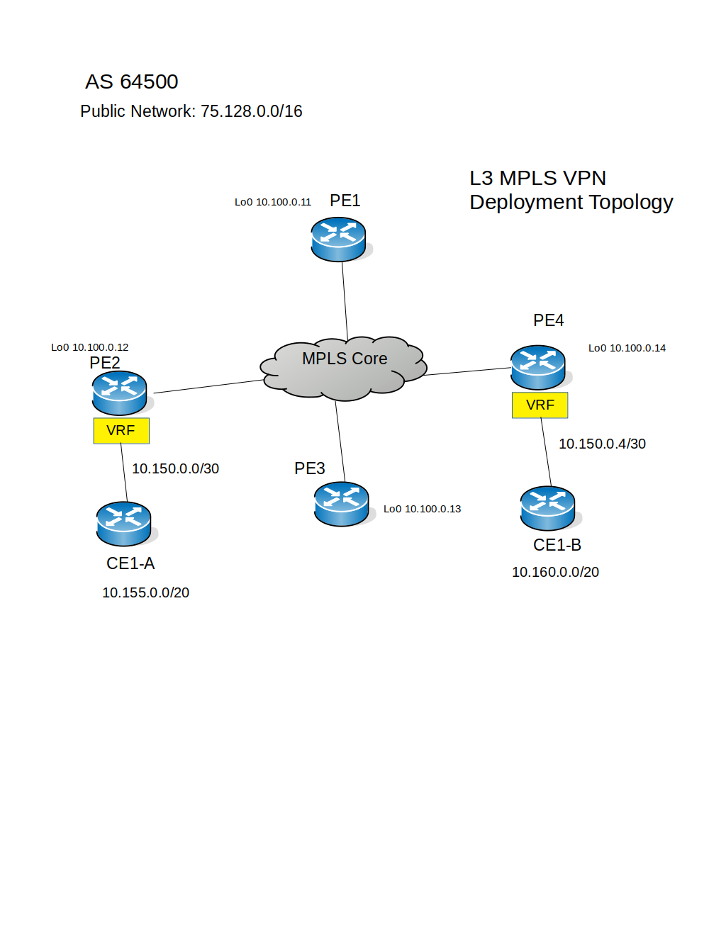
Continue the series of CE-PE Routing in this lab customer's networks will be propagated over MPLS cloud using static routing between the PE sites and CE locations. The second company needed L3 MPLS VPN service is a mid-size organization with two office locations, has requirements to interconnect two /20 subnets. You will be performing the configuration of VRF, Static routing, and redistribution into the BGP VPNv4 table.
Topology:

Download Lab: EVE-NG | GNS3
Scenario:
New service order has been accepted by ISP's sale department all necessary paperwork has been signed and site survey has been completed, network technicians finished their work on the installation of the communication medium and IPv4 connectivity has been verified, next team of network engineers needs to complete the service order by configuring the MPLS VPN application and deliver robust LAN-to-LAN communication.
Lab tasks:
1. Test connectivity between PE sites and routers at the customer's locations.
2. Configure VRF named CE1 on the routers PE2 and PE4.
3. Assign VRF to the interfaces facing the customer's locations.
4. Configure Static routes to the customer's networks on the router PE2 and PE4 under the CE1 routing instance.
5. Redistribute and verify that customer's networks are present in both PE2 and PE4 BGP VPNv4 tables.
6. Help the customer's routing specialist to configure the default static route pointing to the respective PE router.
7. Verify LAN-to-LAN communications between customer's networks.
Lab procedure:
Task1: Test connectivity between PE sites and routers at the customer's locations.
Step1: On the router PE2, check the current interfaces' IP configurations and ping the CE1-A IPv4 address assigned to the G0/1 interface from the global routing table:
PE2#show ip interface brief
Interface IP-Address OK? Method Status Protocol
GigabitEthernet0/0 10.255.2.163 YES NVRAM administratively down down
GigabitEthernet0/1 10.0.1.6 YES NVRAM up up
GigabitEthernet0/2 10.0.3.6 YES NVRAM up up
GigabitEthernet0/3 10.150.0.2 YES NVRAM up up
PE2#ping 10.150.0.1Type escape sequence to abort.
Sending 5, 100-byte ICMP Echos to 10.150.0.1, timeout is 2 seconds:
.!!!!
Success rate is 80 percent (4/5), round-trip min/avg/max = 1/2/4 ms
PE2#
Step2: On the router PE4, check the current interfaces' IP configurations and ping the CE1-B IPv4 address assigned to the G0/1 interface from the global routing table:
PE4#show ip interface brief
Interface IP-Address OK? Method Status Protocol
GigabitEthernet0/0 10.255.2.165 YES NVRAM administratively down down
GigabitEthernet0/1 10.0.2.6 YES NVRAM up up
GigabitEthernet0/2 10.0.4.6 YES NVRAM up up
GigabitEthernet0/3 10.150.0.6 YES NVRAM up up
PE4#ping 10.150.0.5Type escape sequence to abort.
Sending 5, 100-byte ICMP Echos to 10.150.0.5, timeout is 2 seconds:
.!!!!
Success rate is 80 percent (4/5), round-trip min/avg/max = 1/2/4 ms
PE4#
Task2: Configure VRF named CE1 on the routers PE2 and PE4.
Step1: Configure VRF named CE1 on the router PE2 with the RD 1600:1600, RT export and import 1600:1600, configure RT under the AF IPv4:
PE2(config)#vrf definition CE1
PE2(config-vrf)#rd 1600:1600
PE2(config-vrf)#address-family ipv4 unicast
PE2(config-vrf-af)#route-target export 1600:1600
PE2(config-vrf-af)#route-target import 1600:1600
PE2(config-vrf-af)#
Step2: Configure VRF named CE1 on the router PE4 with the RD 1600:1600, RT export and import 1600:1600, configure RT under the AF IPv4:
PE4(config)#vrf definition CE1
PE4(config-vrf)#rd 1600:1600
PE4(config-vrf)#address-family ipv4 unicast
PE4(config-vrf-af)#route-target export 1600:1600
PE4(config-vrf-af)#route-target import 1600:1600
PE4(config-vrf-af)#
Use command "show vrf brief" and "show vrf detail CE1" to verify VRF proper configuration.
Task3: Assign VRF to the interfaces facing the customer's locations.
Step1: Configure the router PE2:
PE2(config)#interface g0/3
PE2(config-if)#vrf forwarding CE1
PE2(config-if)#ip address 10.150.0.2 255.255.255.252
PE2(config-if)# exit
Step2: Configure the router PE4:
PE4(config)#interface g0/3
PE4(config-if)#vrf forwarding CE1
PE4(config-if)#ip address 10.150.0.6 255.255.255.252
PE4(config-if)# exit
Step3: Check routing table for VRF CE1 and ping from both PE routers the customer's CE routers:
PE2#show ip route vrf CE1
10.0.0.0/8 is variably subnetted, 2 subnets, 2 masks
C 10.150.0.0/30 is directly connected, GigabitEthernet0/3
L 10.150.0.2/32 is directly connected, GigabitEthernet0/3
PE2#ping vrf CE1 10.150.0.1
Type escape sequence to abort.
Sending 5, 100-byte ICMP Echos to 10.150.0.1, timeout is 2 seconds:
.!!!!
Success rate is 80 percent (4/5), round-trip min/avg/max = 2/3/4 ms
PE2#
PE4#show ip route vrf CE1
10.0.0.0/8 is variably subnetted, 2 subnets, 2 masks
C 10.150.0.4/30 is directly connected, GigabitEthernet0/3
L 10.150.0.6/32 is directly connected, GigabitEthernet0/3
PE4#ping vrf CE1 10.150.0.5
Type escape sequence to abort.
Sending 5, 100-byte ICMP Echos to 10.150.0.5, timeout is 2 seconds:
.!!!!
Success rate is 80 percent (4/5), round-trip min/avg/max = 2/2/3 ms
PE4#
Task4: Configure Static routes to the customer's networks on the router PE2 and PE4 under the CE1 routing instance.
Step1: On the router PE2, implement the static route for CE1-A's /20 network:
PE2(config)#ip route 10.155.0.0 255.255.240.0 10.150.0.1
Step2: On the router PE4, implement the static route for CE1-B's /20 network:
PE4(config)#ip route vrf CE1 10.160.0.0 255.255.240.0 10.150.0.5
Step3: Verify static routes in the VRF CE1 routing tables on both PE routers:
PE2#show ip route vrf CE1 static
10.0.0.0/8 is variably subnetted, 3 subnets, 3 masks
S 10.155.0.0/20 [1/0] via 10.150.0.1
PE4#show ip route vrf CE1 static
10.0.0.0/8 is variably subnetted, 3 subnets, 3 masks
S 10.160.0.0/20 [1/0] via 10.150.0.5
Task5: Redistribute and verify that customer's networks are present in both PE2 and PE4 BGP VPNv4 tables.
Step1. Configure redistribution on the router PE2:
PE2(config)#router bgp 64500
PE2(config-router)#address-family ipv4 unicast vrf CE1
PE2(config-router-af)#redistribute static
Step2. Configure redistribution on the router PE4:
PE4(config)#router bgp 64500
PE4(config-router)#address-family ipv4 unicast vrf CE1
PE4(config-router-af)#redistribute static
Step3. Verify BGP VPNv4 tables and CE1 routing tables on both PE routers:
PE2#show bgp vpnv4 unicast vrf CE1
Network Next Hop Metric LocPrf Weight Path
Route Distinguisher: 1600:1600 (default for vrf CE1)
*> 10.155.0.0/20 10.150.0.1 0 32768 ?
*>i 10.160.0.0/20 10.100.0.14 0 100 0 ?
PE2#show ip route vrf CE1
10.0.0.0/8 is variably subnetted, 4 subnets, 3 masks
C 10.150.0.0/30 is directly connected, GigabitEthernet0/3
L 10.150.0.2/32 is directly connected, GigabitEthernet0/3
S 10.155.0.0/20 [1/0] via 10.150.0.1
B 10.160.0.0/20 [200/0] via 10.100.0.14, 00:02:23
PE4#show bgp vpnv4 unicast vrf CE1
Network Next Hop Metric LocPrf Weight Path
Route Distinguisher: 1600:1600 (default for vrf CE1)
*>i 10.155.0.0/20 10.100.0.12 0 100 0 ?
*> 10.160.0.0/20 10.150.0.5 0 32768 ?
PE4#show ip route vrf CE1
10.0.0.0/8 is variably subnetted, 4 subnets, 3 masks
C 10.150.0.4/30 is directly connected, GigabitEthernet0/3
L 10.150.0.6/32 is directly connected, GigabitEthernet0/3
B 10.155.0.0/20 [200/0] via 10.100.0.12, 00:12:03
S 10.160.0.0/20 [1/0] via 10.150.0.5
Now that all routes have been propagated across MPLS cloud it time to configure CE routers to access each other networks.
Task6: Help the customer's routing specialist to configure the default static route pointing to the respective PE router.
Step1: Configure default static route on the router CE1-A, use router's PE2 IP address assigned to the interface G0/3 as the next-hop:
CE1-A(config)#ip route 0.0.0.0 0.0.0.0 10.150.0.2
Step2: Configure default static route on the router CE1-B, use router's PE4 IP address assigned to the interface G0/3 as the next-hop:
CE1-B(config)#ip route 0.0.0.0 0.0.0.0 10.150.0.6
Task7: Verify LAN-to-LAN communications between customer's networks.
Step1. Ping from CE1-A, IP address of loopback0 interface on the router CE1-B sourcing from loopback0 interface:
CE1-A#ping 10.160.0.1 source lo0
Type escape sequence to abort.
Sending 5, 100-byte ICMP Echos to 10.160.0.1, timeout is 2 seconds:
Packet sent with a source address of 10.155.0.1
!!!!!
Success rate is 100 percent (5/5), round-trip min/avg/max = 7/7/10 ms
CE1-A#
Step2. Ping from CE1-B, IP address of loopback0 interface on the router CE1-A sourcing from loopback0 interface:
CE1-B#ping 10.155.0.1 source lo0
Type escape sequence to abort.
Sending 5, 100-byte ICMP Echos to 10.155.0.1, timeout is 2 seconds:
Packet sent with a source address of 10.160.0.1
!!!!!
Success rate is 100 percent (5/5), round-trip min/avg/max = 6/7/9 ms
CE1-B#
It seems that connectivity between LAN networks functioning properly.
Summary:
Another CE-PE routing method has been learned, this time static routes were installed into BGP VPNv4 structure by means of injecting VRF static routes into MPLS cloud. This configuration is suitable when the customer's small prefixes can be summarized into several large routes like in this lab for example networks with /20 prefixes were propagated over MPLS infrastructure. In the course of the next several labs, more CE-PE routing methods using dynamic routing protocols will be discovered.
VIRL: IOSv 15.7
EVE-NG: Cisco vIOS Router vios-15.6
GNS3: vios-adventerprisek9-m.vmdk.SPA.156-2.T
Description:
Continue the series of CE-PE Routing in this lab customer's networks will be propagated over MPLS cloud using static routing between the PE sites and CE locations. The second company needed L3 MPLS VPN service is a mid-size organization with two office locations, has requirements to interconnect two /20 subnets. You will be performing the configuration of VRF, Static routing, and redistribution into the BGP VPNv4 table.
Topology:
Download Lab: EVE-NG | GNS3
Scenario:
New service order has been accepted by ISP's sale department all necessary paperwork has been signed and site survey has been completed, network technicians finished their work on the installation of the communication medium and IPv4 connectivity has been verified, next team of network engineers needs to complete the service order by configuring the MPLS VPN application and deliver robust LAN-to-LAN communication.
Lab tasks:
1. Test connectivity between PE sites and routers at the customer's locations.
2. Configure VRF named CE1 on the routers PE2 and PE4.
3. Assign VRF to the interfaces facing the customer's locations.
4. Configure Static routes to the customer's networks on the router PE2 and PE4 under the CE1 routing instance.
5. Redistribute and verify that customer's networks are present in both PE2 and PE4 BGP VPNv4 tables.
6. Help the customer's routing specialist to configure the default static route pointing to the respective PE router.
7. Verify LAN-to-LAN communications between customer's networks.
Lab procedure:
Task1: Test connectivity between PE sites and routers at the customer's locations.
Step1: On the router PE2, check the current interfaces' IP configurations and ping the CE1-A IPv4 address assigned to the G0/1 interface from the global routing table:
PE2#show ip interface brief
Interface IP-Address OK? Method Status Protocol
GigabitEthernet0/0 10.255.2.163 YES NVRAM administratively down down
GigabitEthernet0/1 10.0.1.6 YES NVRAM up up
GigabitEthernet0/2 10.0.3.6 YES NVRAM up up
GigabitEthernet0/3 10.150.0.2 YES NVRAM up up
PE2#ping 10.150.0.1Type escape sequence to abort.
Sending 5, 100-byte ICMP Echos to 10.150.0.1, timeout is 2 seconds:
.!!!!
Success rate is 80 percent (4/5), round-trip min/avg/max = 1/2/4 ms
PE2#
Step2: On the router PE4, check the current interfaces' IP configurations and ping the CE1-B IPv4 address assigned to the G0/1 interface from the global routing table:
PE4#show ip interface brief
Interface IP-Address OK? Method Status Protocol
GigabitEthernet0/0 10.255.2.165 YES NVRAM administratively down down
GigabitEthernet0/1 10.0.2.6 YES NVRAM up up
GigabitEthernet0/2 10.0.4.6 YES NVRAM up up
GigabitEthernet0/3 10.150.0.6 YES NVRAM up up
PE4#ping 10.150.0.5Type escape sequence to abort.
Sending 5, 100-byte ICMP Echos to 10.150.0.5, timeout is 2 seconds:
.!!!!
Success rate is 80 percent (4/5), round-trip min/avg/max = 1/2/4 ms
PE4#
Task2: Configure VRF named CE1 on the routers PE2 and PE4.
Step1: Configure VRF named CE1 on the router PE2 with the RD 1600:1600, RT export and import 1600:1600, configure RT under the AF IPv4:
PE2(config)#vrf definition CE1
PE2(config-vrf)#rd 1600:1600
PE2(config-vrf)#address-family ipv4 unicast
PE2(config-vrf-af)#route-target export 1600:1600
PE2(config-vrf-af)#route-target import 1600:1600
PE2(config-vrf-af)#
Step2: Configure VRF named CE1 on the router PE4 with the RD 1600:1600, RT export and import 1600:1600, configure RT under the AF IPv4:
PE4(config)#vrf definition CE1
PE4(config-vrf)#rd 1600:1600
PE4(config-vrf)#address-family ipv4 unicast
PE4(config-vrf-af)#route-target export 1600:1600
PE4(config-vrf-af)#route-target import 1600:1600
PE4(config-vrf-af)#
Use command "show vrf brief" and "show vrf detail CE1" to verify VRF proper configuration.
Task3: Assign VRF to the interfaces facing the customer's locations.
Step1: Configure the router PE2:
PE2(config)#interface g0/3
PE2(config-if)#vrf forwarding CE1
PE2(config-if)#ip address 10.150.0.2 255.255.255.252
PE2(config-if)# exit
Step2: Configure the router PE4:
PE4(config)#interface g0/3
PE4(config-if)#vrf forwarding CE1
PE4(config-if)#ip address 10.150.0.6 255.255.255.252
PE4(config-if)# exit
Step3: Check routing table for VRF CE1 and ping from both PE routers the customer's CE routers:
PE2#show ip route vrf CE1
10.0.0.0/8 is variably subnetted, 2 subnets, 2 masks
C 10.150.0.0/30 is directly connected, GigabitEthernet0/3
L 10.150.0.2/32 is directly connected, GigabitEthernet0/3
PE2#ping vrf CE1 10.150.0.1
Type escape sequence to abort.
Sending 5, 100-byte ICMP Echos to 10.150.0.1, timeout is 2 seconds:
.!!!!
Success rate is 80 percent (4/5), round-trip min/avg/max = 2/3/4 ms
PE2#
PE4#show ip route vrf CE1
10.0.0.0/8 is variably subnetted, 2 subnets, 2 masks
C 10.150.0.4/30 is directly connected, GigabitEthernet0/3
L 10.150.0.6/32 is directly connected, GigabitEthernet0/3
PE4#ping vrf CE1 10.150.0.5
Type escape sequence to abort.
Sending 5, 100-byte ICMP Echos to 10.150.0.5, timeout is 2 seconds:
.!!!!
Success rate is 80 percent (4/5), round-trip min/avg/max = 2/2/3 ms
PE4#
Task4: Configure Static routes to the customer's networks on the router PE2 and PE4 under the CE1 routing instance.
Step1: On the router PE2, implement the static route for CE1-A's /20 network:
PE2(config)#ip route 10.155.0.0 255.255.240.0 10.150.0.1
Step2: On the router PE4, implement the static route for CE1-B's /20 network:
PE4(config)#ip route vrf CE1 10.160.0.0 255.255.240.0 10.150.0.5
Step3: Verify static routes in the VRF CE1 routing tables on both PE routers:
PE2#show ip route vrf CE1 static
10.0.0.0/8 is variably subnetted, 3 subnets, 3 masks
S 10.155.0.0/20 [1/0] via 10.150.0.1
PE4#show ip route vrf CE1 static
10.0.0.0/8 is variably subnetted, 3 subnets, 3 masks
S 10.160.0.0/20 [1/0] via 10.150.0.5
Task5: Redistribute and verify that customer's networks are present in both PE2 and PE4 BGP VPNv4 tables.
Step1. Configure redistribution on the router PE2:
PE2(config)#router bgp 64500
PE2(config-router)#address-family ipv4 unicast vrf CE1
PE2(config-router-af)#redistribute static
Step2. Configure redistribution on the router PE4:
PE4(config)#router bgp 64500
PE4(config-router)#address-family ipv4 unicast vrf CE1
PE4(config-router-af)#redistribute static
Step3. Verify BGP VPNv4 tables and CE1 routing tables on both PE routers:
PE2#show bgp vpnv4 unicast vrf CE1
Network Next Hop Metric LocPrf Weight Path
Route Distinguisher: 1600:1600 (default for vrf CE1)
*> 10.155.0.0/20 10.150.0.1 0 32768 ?
*>i 10.160.0.0/20 10.100.0.14 0 100 0 ?
PE2#show ip route vrf CE1
10.0.0.0/8 is variably subnetted, 4 subnets, 3 masks
C 10.150.0.0/30 is directly connected, GigabitEthernet0/3
L 10.150.0.2/32 is directly connected, GigabitEthernet0/3
S 10.155.0.0/20 [1/0] via 10.150.0.1
B 10.160.0.0/20 [200/0] via 10.100.0.14, 00:02:23
PE4#show bgp vpnv4 unicast vrf CE1
Network Next Hop Metric LocPrf Weight Path
Route Distinguisher: 1600:1600 (default for vrf CE1)
*>i 10.155.0.0/20 10.100.0.12 0 100 0 ?
*> 10.160.0.0/20 10.150.0.5 0 32768 ?
PE4#show ip route vrf CE1
10.0.0.0/8 is variably subnetted, 4 subnets, 3 masks
C 10.150.0.4/30 is directly connected, GigabitEthernet0/3
L 10.150.0.6/32 is directly connected, GigabitEthernet0/3
B 10.155.0.0/20 [200/0] via 10.100.0.12, 00:12:03
S 10.160.0.0/20 [1/0] via 10.150.0.5
Now that all routes have been propagated across MPLS cloud it time to configure CE routers to access each other networks.
Task6: Help the customer's routing specialist to configure the default static route pointing to the respective PE router.
Step1: Configure default static route on the router CE1-A, use router's PE2 IP address assigned to the interface G0/3 as the next-hop:
CE1-A(config)#ip route 0.0.0.0 0.0.0.0 10.150.0.2
Step2: Configure default static route on the router CE1-B, use router's PE4 IP address assigned to the interface G0/3 as the next-hop:
CE1-B(config)#ip route 0.0.0.0 0.0.0.0 10.150.0.6
Task7: Verify LAN-to-LAN communications between customer's networks.
Step1. Ping from CE1-A, IP address of loopback0 interface on the router CE1-B sourcing from loopback0 interface:
CE1-A#ping 10.160.0.1 source lo0
Type escape sequence to abort.
Sending 5, 100-byte ICMP Echos to 10.160.0.1, timeout is 2 seconds:
Packet sent with a source address of 10.155.0.1
!!!!!
Success rate is 100 percent (5/5), round-trip min/avg/max = 7/7/10 ms
CE1-A#
Step2. Ping from CE1-B, IP address of loopback0 interface on the router CE1-A sourcing from loopback0 interface:
CE1-B#ping 10.155.0.1 source lo0
Type escape sequence to abort.
Sending 5, 100-byte ICMP Echos to 10.155.0.1, timeout is 2 seconds:
Packet sent with a source address of 10.160.0.1
!!!!!
Success rate is 100 percent (5/5), round-trip min/avg/max = 6/7/9 ms
CE1-B#
It seems that connectivity between LAN networks functioning properly.
Summary:
Another CE-PE routing method has been learned, this time static routes were installed into BGP VPNv4 structure by means of injecting VRF static routes into MPLS cloud. This configuration is suitable when the customer's small prefixes can be summarized into several large routes like in this lab for example networks with /20 prefixes were propagated over MPLS infrastructure. In the course of the next several labs, more CE-PE routing methods using dynamic routing protocols will be discovered.

Comments
Post a Comment