MPLS Lab 002 Configuring MP-BGP PE-PE Routing
Image requirements:
VIRL: IOSv 15.7
EVE-NG: Cisco vIOS Router vios-15.6
GNS3: vios-adventerprisek9-m.vmdk.SPA.156-2.T
Description:
In this lab network engineers will configure MP-BGP VPNv4 address-family to establish peer-to-peer VPN tunnels between the all four PE routers in the full-meshed configuration, then to test the proper operation of the VPNv4 tunnels, test VRF will be configured to check if L3 MPLS VPN implementation is working.
Topology:
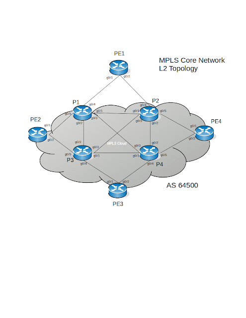
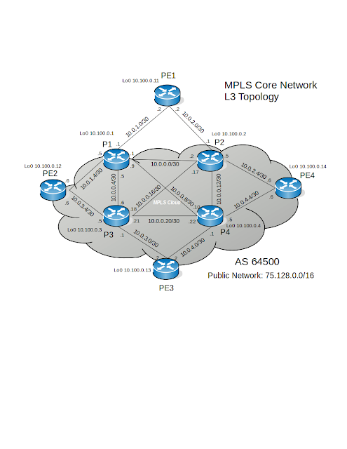
Download Lab: VIRL | EVE-NG | GNS3
Scenario:
In the previous lab, the MPLS core infrastructure has been deployed, now that packet switching between PE nodes occur using labels, the network is ready to begin work on the BGP part of the L3 MPLS VPN implementation. You will configure MP-BGP, starting with enabling BGP protocol, manually establishing neighborships between PE routers using loopback0 interfaces' IP addresses, configuring address-family for VPNv4 and finally create VRF for testing purposes. After successful ping between IP networks of VRFs, the tasks in this lab will be completed and the topology will be ready to interconnect customers' networks.
Tasks:
1. Verify that PE routers able to reach each other loopback0's IP addresses, using labels.
2. Configure MP-BGP protocol in the topology, only on the PE routers.
3. Configure multiple VRFs on all PE routers to test the L3 MPLS VPN application.
4. Verify L3 MPLS VPN implementation.
Procedure:
Task1: Confirm that MPLS working as intended.
Step1: Verify the MPLS forwarding table on every PE router.
Example:
PE1#show mpls forwarding-table
Local Outgoing Prefix Bytes Label Outgoing Next Hop
Label Label or Tunnel Id Switched interface
1100 Pop Label 10.0.0.0/30 0 Gi0/1 10.0.1.1
Pop Label 10.0.0.0/30 0 Gi0/2 10.0.2.1
1101 Pop Label 10.0.0.4/30 0 Gi0/1 10.0.1.1
1102 Pop Label 10.0.0.8/30 0 Gi0/1 10.0.1.1
1103 Pop Label 10.0.0.12/30 0 Gi0/2 10.0.2.1
1104 Pop Label 10.0.0.16/30 0 Gi0/2 10.0.2.1
1105 102 10.0.0.20/30 0 Gi0/1 10.0.1.1
202 10.0.0.20/30 0 Gi0/2 10.0.2.1
1106 Pop Label 10.0.1.4/30 0 Gi0/1 10.0.1.1
1107 Pop Label 10.0.2.4/30 0 Gi0/2 10.0.2.1
1108 105 10.0.3.0/30 0 Gi0/1 10.0.1.1
205 10.0.3.0/30 0 Gi0/2 10.0.2.1
1109 106 10.0.3.4/30 0 Gi0/1 10.0.1.1
206 10.0.3.4/30 0 Gi0/2 10.0.2.1
1110 107 10.0.4.0/30 0 Gi0/1 10.0.1.1
207 10.0.4.0/30 0 Gi0/2 10.0.2.1
1111 108 10.0.4.4/30 0 Gi0/1 10.0.1.1
208 10.0.4.4/30 0 Gi0/2 10.0.2.1
1112 Pop Label 10.100.0.1/32 0 Gi0/1 10.0.1.1
1113 Pop Label 10.100.0.2/32 0 Gi0/2 10.0.2.1
Local Outgoing Prefix Bytes Label Outgoing Next Hop
Label Label or Tunnel Id Switched interface
1114 110 10.100.0.3/32 0 Gi0/1 10.0.1.1
210 10.100.0.3/32 0 Gi0/2 10.0.2.1
1115 111 10.100.0.4/32 0 Gi0/1 10.0.1.1
211 10.100.0.4/32 0 Gi0/2 10.0.2.1
1116 113 10.100.0.12/32 0 Gi0/1 10.0.1.1
1117 114 10.100.0.13/32 0 Gi0/1 10.0.1.1
214 10.100.0.13/32 0 Gi0/2 10.0.2.1
1118 215 10.100.0.14/32 0 Gi0/2 10.0.2.1
Looking in the output at local and remote labels for IP prefixes of loopback0 intefaces for PE routers proves that PE1 router using MPLS switching to reach these destinations.
Step2: Traceroute loopback0 interfaces' IP addresses of each PE router from PE1:
Example:
PE1#traceroute 10.100.0.13 probe 1
Type escape sequence to abort.
Tracing the route to 10.100.0.13
VRF info: (vrf in name/id, vrf out name/id)
1 10.0.1.1 [MPLS: Label 114 Exp 0] 7 msec
2 10.0.0.18 [MPLS: Label 314 Exp 0] 6 msec
3 10.0.4.2 6 msec
PE1#
MPLS labels appear in the traceroute output indicating that to reach the PE3's loopback0 interface label switching was used.
Task2: Implement a peer-to-peer VPN using MP-BGP.
Step1: Enable BGP protocol with AS 64500, setup the full-mesh neighborships between PE routers:
PE1(config)#router bgp 64500
PE1(config-router)#bgp router-id 10.100.0.11
PE1(config-router)#neighbor 10.100.0.12 remote-as 64500
PE1(config-router)#neighbor 10.100.0.12 update-source lo0
PE1(config-router)#neighbor 10.100.0.13 remote-as 64500
PE1(config-router)#neighbor 10.100.0.13 update-source lo0
PE1(config-router)#neighbor 10.100.0.14 remote-as 64500
PE1(config-router)#neighbor 10.100.0.14 update-source lo0
PE1(config-router)#
Repeat mirror configuration on the routers PE2, PE3, and PE4.
For now, you should have bgp running-config look like this:
PE1#show running-config | section bgp
router bgp 64500
bgp router-id 10.100.0.11
bgp log-neighbor-changes
neighbor 10.100.0.12 remote-as 64500
neighbor 10.100.0.12 update-source Loopback0
neighbor 10.100.0.13 remote-as 64500
neighbor 10.100.0.13 update-source Loopback0
neighbor 10.100.0.14 remote-as 64500
neighbor 10.100.0.14 update-source Loopback0
PE1#
After you complete configuring the rest of the PE routers you will be able to see BGP neighborships come up:
PE1#show bgp ipv4 unicast summary
BGP router identifier 10.100.0.11, local AS number 64500
BGP table version is 1, main routing table version 1
Neighbor V AS MsgRcvd MsgSent TblVer InQ OutQ Up/Down State/PfxRcd
10.100.0.12 4 64500 12 12 1 0 0 00:07:57 0
10.100.0.13 4 64500 10 8 1 0 0 00:05:57 0
10.100.0.14 4 64500 8 6 1 0 0 00:03:49 0
PE1#
Step2: Activate each existing peer under the VPNv4 address-family configuration and enable BGP router to send extended community capabilities:
PE1(config)#router bgp 64500
PE1(config-router)#address-family vpnv4 unicast
PE1(config-router-af)#neighbor 10.100.0.12 activate
PE1(config-router-af)#neighbor 10.100.0.12 send-community extended
PE1(config-router-af)#neighbor 10.100.0.13 activate
PE1(config-router-af)#neighbor 10.100.0.13 send-community extended
PE1(config-router-af)#neighbor 10.100.0.14 activate
PE1(config-router-af)#neighbor 10.100.0.14 send-community extended
PE1(config-router-af)#
Repeat mirror configuration on the routers PE2, PE3, and PE4.
Step3: Verify MP-BGP VPNv4 address-family.
Check on the local router if its peers support the VPNv4 capabilities:
PE1#show ip bgp neighbors | section capabilities
Neighbor capabilities:
Route refresh: advertised and received(new)
Four-octets ASN Capability: advertised and received
Address family IPv4 Unicast: advertised and received
Address family VPNv4 Unicast: advertised and received
Enhanced Refresh Capability: advertised and received
Multisession Capability:
Stateful switchover support enabled: NO for session 1
The output show parameters for all 3 peers.
Verify that router established TCP sessions with other BGP enabled neighbors:
PE1#show control-plane host open-ports
Active internet connections (servers and established)
Prot Local Address Foreign Address Service State
tcp *:19487 10.100.0.1:646 IOS host service ESTABLIS
tcp *:23 *:0 Telnet LISTEN
tcp *:179 10.100.0.14:47479 BGP ESTABLIS
tcp *:179 10.100.0.13:15323 BGP ESTABLIS
tcp *:179 10.100.0.12:38177 BGP ESTABLIS
tcp *:179 *:0 BGP LISTEN
tcp *:179 *:0 BGP LISTEN
tcp *:179 *:0 BGP LISTEN
tcp *:49206 10.100.0.2:646 IOS host service ESTABLIS
udp *:3503 *:0 LSPV Echo LISTEN
In the output you can see that three other neighbors establsihed BGP sessions to PE1 router.
Finally, verify the BGP VPNv4 neighbors:
PE1#show bgp vpnv4 unicast all summary
BGP router identifier 10.100.0.11, local AS number 64500
BGP table version is 1, main routing table version 1
Neighbor V AS MsgRcvd MsgSent TblVer InQ OutQ Up/Down State/PfxRcd
10.100.0.12 4 64500 23 23 1 0 0 00:17:17 0
10.100.0.13 4 64500 21 18 1 0 0 00:15:21 0
10.100.0.14 4 64500 14 13 1 0 0 00:10:49 0
PE1#
All three peers are up but not yet prefixes have been redistributed into VPNv4 Cloud.
Task3: Before connecting the customers' networks, it is a good idea to configure the VRF and verify the operation of L3 MPLS VPN services in the testing environment.
Step1: Configure VRFs. Three VRFs will be used to test the VPN. VRFs are PE2-PE1_T, PE2-PE3_T, PE2-PE4_T. All VRFs originating at PE2 router.
List of Actions:
a. Create VRFs
b. Assign Route Distinguisher to each VRF
c. Enter IPv4 address-family
d. Configure import and export Route Targets.
Configuring VRFs on the router PE2:
PE2(config)#vrf definition PE2-PE1_T
PE2(config-vrf)#rd 1000:1001
PE2(config-vrf)#address-family ipv4 unicast
PE2(config-vrf-af)#route-target export 1000:1001
PE2(config-vrf-af)#route-target import 1000:1001
PE2(config-vrf-af)#exit
PE2(config)#vrf definition PE2-PE3_T
PE2(config-vrf)#rd 2000:2001
PE2(config-vrf)#address-family ipv4 unicast
PE2(config-vrf-af)#route-target export 2000:2001
PE2(config-vrf-af)#route-target import 2000:2001
PE2(config-vrf-af)#exit
PE2(config)#vrf definition PE2-PE4_T
PE2(config-vrf)#rd 3000:3001
PE2(config-vrf)#address-family ipv4 unicast
PE2(config-vrf-af)#route-target export 3000:3001
PE2(config-vrf-af)#route-target import 3000:3001
PE2(config-vrf-af)#exit
Configuring VRFs on the router PE1:
PE1(config)#vrf definition PE2-PE1_T
PE1(config-vrf)#rd 1000:1001
PE1(config-vrf)#address-family ipv4 unicast
PE1(config-vrf-af)#route-target export 1000:1001
PE1(config-vrf-af)#route-target import 1000:1001
PE1(config-vrf-af)#exit
Configuring VRFs on the router PE3:
PE3(config)#vrf definition PE2-PE3_T
PE3(config-vrf)#rd 2000:2001
PE3(config-vrf)#address-family ipv4 unicast
PE3(config-vrf-af)#route-target export 2000:2001
PE3(config-vrf-af)#route-target import 2000:2001
PE3(config-vrf-af)#exit
Configuring VRFs on the router PE4:
PE4(config)#vrf definition PE2-PE4_T
PE4(config-vrf)#rd 3000:3001
PE4(config-vrf)#address-family ipv4 unicast
PE4(config-vrf-af)#route-target export 3000:3001
PE4(config-vrf-af)#route-target import 3000:3001
PE4(config-vrf-af)#exit
Step2: Verify VRFs:
PE2#show vrf brief
Name Default RD Protocols Interfaces
Mgmt-intf <not set> ipv4,ipv6 Gi0/0
PE2-PE1_T 1000:1001 ipv4
PE2-PE3_T 2000:2001 ipv4
PE2-PE4_T 3000:3001 ipv4
PE2#show vrf detail PE2-PE1_T
VRF PE2-PE1_T (VRF Id = 2); default RD 1000:1001; default VPNID <not set>
New CLI format, supports multiple address-families
Flags: 0x180C
No interfaces
Address family ipv4 unicast (Table ID = 0x2):
Flags: 0x0
Export VPN route-target communities
RT:1000:1001
Import VPN route-target communities
RT:1000:1001
No import route-map
No global export route-map
No export route-map
VRF label distribution protocol: not configured
VRF label allocation mode: per-prefix
Address family ipv6 unicast not active
Address family ipv4 multicast not active
Step3: Configure Loopback interfaces with appropriate VRFs assign to them.
Three Loopback interfaces needed on the router PE2 for each VRF:
PE2(config)#interface loopback 1000
PE2(config-if)#vrf forwarding PE2-PE1_T
PE2(config-if)#ip address 172.16.255.1 255.255.255.255
PE2(config-if)#end
PE2(config)#interface loopback 2000
PE2(config-if)#vrf forwarding PE2-PE3_T
PE2(config-if)#ip address 172.16.255.2 255.255.255.255
PE2(config-if)#end
PE2(config)#interface loopback 3000
PE2(config-if)#vrf forwarding PE2-PE4_T
PE2(config-if)#ip address 172.16.255.3 255.255.255.255
PE2(config-if)#end
PE1(config)#interface loopback 1000
PE1(config-if)#vrf forwarding PE2-PE1_T
PE1(config-if)#ip address 172.17.255.1 255.255.255.255
PE1(config-if)#end
PE3(config)#interface loopback 2000
PE3(config-if)#vrf forwarding PE2-PE3_T
PE3(config-if)#ip address 172.18.255.1 255.255.255.255
PE3(config-if)#end
PE4(config)#interface loopback 3000
PE4(config-if)#vrf forwarding PE2-PE4_T
PE4(config-if)#ip address 172.19.255.1 255.255.255.255
PE4(config-if)#end
Verify ip routing table for VRF:
PE2#show ip route vrf PE2-PE1_T
Routing Table: PE2-PE1_T
Codes: L - local, C - connected, S - static, R - RIP, M - mobile, B - BGP
D - EIGRP, EX - EIGRP external, O - OSPF, IA - OSPF inter area
N1 - OSPF NSSA external type 1, N2 - OSPF NSSA external type 2
E1 - OSPF external type 1, E2 - OSPF external type 2
i - IS-IS, su - IS-IS summary, L1 - IS-IS level-1, L2 - IS-IS level-2
ia - IS-IS inter area, * - candidate default, U - per-user static route
o - ODR, P - periodic downloaded static route, H - NHRP, l - LISP
a - application route
+ - replicated route, % - next hop override, p - overrides from PfR
Gateway of last resort is not set
172.16.0.0/32 is subnetted, 1 subnets
C 172.16.255.1 is directly connected, Loopback1000
Step4: Now that loopback interfaces are configured, you need to put VRFs' networks onto the VPNv4, to accomplish this you need to redistribute connected networks into BGP AS 64500.
First, use the BGP VPNv4 command to verify that there are no prefixes in the VPNv4 BGP table:
PE2#show bgp vpnv4 unicast all
the empty output shows that there are no prefixes.
Configure router PE2 first since this node is the hub for multiple VRFs, under BGP global configuration you need to enter IPv4 address-family for each VRF and configure redistribute connected.
This is how BGP configured now:
PE2#show running-config | section bgp
router bgp 64500
bgp router-id 10.100.0.12
bgp log-neighbor-changes
neighbor 10.100.0.11 remote-as 64500
neighbor 10.100.0.11 update-source Loopback0
neighbor 10.100.0.13 remote-as 64500
neighbor 10.100.0.13 update-source Loopback0
neighbor 10.100.0.14 remote-as 64500
neighbor 10.100.0.14 update-source Loopback0
!
address-family vpnv4
neighbor 10.100.0.11 activate
neighbor 10.100.0.11 send-community extended
neighbor 10.100.0.13 activate
neighbor 10.100.0.13 send-community extended
neighbor 10.100.0.14 activate
neighbor 10.100.0.14 send-community extended
exit-address-family
Redistribute VRFs' networks into BGP VPNv4 table on the router PE2:
PE2(config)#router bgp 64500
PE2(config-router)#address-family ipv4 unicast vrf PE2-PE1_T
PE2(config-router-af)#redistribute connected
PE2(config-router-af)#exit
PE2(config-router)#address-family ipv4 unicast vrf PE2-PE3_T
PE2(config-router-af)#redistribute connected
PE2(config-router-af)#exit
PE2(config-router)#address-family ipv4 unicast vrf PE2-PE4_T
PE2(config-router-af)#redistribute connected
PE2(config-router-af)#end
Verify the BGP VPNv4 table again:
PE2#show bgp vpnv4 unicast all
BGP table version is 4, local router ID is 10.100.0.12
Status codes: s suppressed, d damped, h history, * valid, > best, i - internal,
r RIB-failure, S Stale, m multipath, b backup-path, f RT-Filter,
x best-external, a additional-path, c RIB-compressed,
t secondary path,
Origin codes: i - IGP, e - EGP, ? - incomplete
RPKI validation codes: V valid, I invalid, N Not found
Network Next Hop Metric LocPrf Weight Path
Route Distinguisher: 1000:1001 (default for vrf PE2-PE1_T)
*> 172.16.255.1/32 0.0.0.0 0 32768 ?
Route Distinguisher: 2000:2001 (default for vrf PE2-PE3_T)
*> 172.16.255.2/32 0.0.0.0 0 32768 ?
Route Distinguisher: 3000:3001 (default for vrf PE2-PE4_T)
*> 172.16.255.3/32 0.0.0.0 0 32768 ?
PE2#
The output shows that there are prefixes in the table for each VRF, the 0.0.0.0 under the next-hop indicates that prefixes originated locally. You can see the prefixes of each individual VRF by specifying VRF's name instead of "all" argument.
Verify if the prefix of VRF PE2-PE1_T on the PE2 is in the BGP VPNv4 table on the router PE1:
PE1#show bgp vpnv4 unicast vrf PE2-PE1_T
BGP table version is 3, local router ID is 10.100.0.11
Status codes: s suppressed, d damped, h history, * valid, > best, i - internal,
r RIB-failure, S Stale, m multipath, b backup-path, f RT-Filter,
x best-external, a additional-path, c RIB-compressed,
t secondary path,
Origin codes: i - IGP, e - EGP, ? - incomplete
RPKI validation codes: V valid, I invalid, N Not found
Network Next Hop Metric LocPrf Weight Path
Route Distinguisher: 1000:1001 (default for vrf PE2-PE1_T)
*>i 172.16.255.1/32 10.100.0.12 0 100 0 ?
The prefix from PE2 is in the PE1's BGP VPNv4 table, now it is important to know if the prefix got into VRF's PE2-PE1_T routing table on the router PE1:
PE1#show ip route vrf PE2-PE1_T
Routing Table: PE2-PE1_T
Codes: L - local, C - connected, S - static, R - RIP, M - mobile, B - BGP
D - EIGRP, EX - EIGRP external, O - OSPF, IA - OSPF inter area
N1 - OSPF NSSA external type 1, N2 - OSPF NSSA external type 2
E1 - OSPF external type 1, E2 - OSPF external type 2
i - IS-IS, su - IS-IS summary, L1 - IS-IS level-1, L2 - IS-IS level-2
ia - IS-IS inter area, * - candidate default, U - per-user static route
o - ODR, P - periodic downloaded static route, H - NHRP, l - LISP
a - application route
+ - replicated route, % - next hop override, p - overrides from PfR
Gateway of last resort is not set
172.16.0.0/32 is subnetted, 1 subnets
B 172.16.255.1 [200/0] via 10.100.0.12, 00:15:29
172.17.0.0/32 is subnetted, 1 subnets
C 172.17.255.1 is directly connected, Loopback1000
Repeat similar verification on the rest of PE routers.
Now in order to have two-way communication between Loopback interfaces in the same VRFs on the opposite sides of MPLS cloud the PE1, PE3, and PE4 have to redistribute their VRFs' networks into BGP VPNv4 table.
Example:
PE1(config)#router bgp 64500
PE1(config-router)#address-family ipv4 unicast vrf PE2-PE1_T
PE1(config-router-af)#redistribute connected
PE1(config-router-af)#end
PE3(config)#router bgp 64500
PE3(config-router)#address-family ipv4 unicast vrf PE2-PE3_T
PE3(config-router-af)#redistribute connected
PE3(config-router-af)#end
PE4(config)#router bgp 64500
PE4(config-router)#address-family ipv4 unicast vrf PE2-PE4_T
PE4(config-router-af)#redistribute connected
PE4(config-router-af)#end
Save configurations on the spoke PE routers and go to PE2 to verify the redistribution:
PE2#show bgp vpnv4 unicast all
BGP table version is 10, local router ID is 10.100.0.12
Status codes: s suppressed, d damped, h history, * valid, > best, i - internal,
r RIB-failure, S Stale, m multipath, b backup-path, f RT-Filter,
x best-external, a additional-path, c RIB-compressed,
t secondary path,
Origin codes: i - IGP, e - EGP, ? - incomplete
RPKI validation codes: V valid, I invalid, N Not found
Network Next Hop Metric LocPrf Weight Path
Route Distinguisher: 1000:1001 (default for vrf PE2-PE1_T)
*> 172.16.255.1/32 0.0.0.0 0 32768 ?
*>i 172.17.255.1/32 10.100.0.11 0 100 0 ?
Route Distinguisher: 2000:2001 (default for vrf PE2-PE3_T)
*> 172.16.255.2/32 0.0.0.0 0 32768 ?
*>i 172.18.255.1/32 10.100.0.13 0 100 0 ?
Route Distinguisher: 3000:3001 (default for vrf PE2-PE4_T)
*> 172.16.255.3/32 0.0.0.0 0 32768 ?
*>i 172.19.255.1/32 10.100.0.14 0 100 0 ?
PE2#
As you can see that now, for each VRF there is the additional prefix, coming from the other PE routers.
Task4: Verify L3 MPLS VPN.
From PE2's VRF PE2-PE1_T ping loopback1000 interfaces' IP address on the router PE1:
PE2#ping vrf PE2-PE1_T 172.17.255.1
Type escape sequence to abort.
Sending 5, 100-byte ICMP Echos to 172.17.255.1, timeout is 2 seconds:
!!!!!
Success rate is 100 percent (5/5), round-trip min/avg/max = 4/4/5 ms
PE2#
From PE2's VRF PE2-PE3_T ping loopback2000 interfaces' IP address on the router PE3:
PE2#ping vrf PE2-PE3_T 172.18.255.1
Type escape sequence to abort.
Sending 5, 100-byte ICMP Echos to 172.18.255.1, timeout is 2 seconds:
!!!!!
Success rate is 100 percent (5/5), round-trip min/avg/max = 3/4/6 ms
PE2#
From PE2's VRF PE2-PE4_T ping loopback3000 interfaces' IP address on the router PE4:
PE2#ping vrf PE2-PE4_T 172.19.255.1
Type escape sequence to abort.
Sending 5, 100-byte ICMP Echos to 172.19.255.1, timeout is 2 seconds:
!!!!!
Success rate is 100 percent (5/5), round-trip min/avg/max = 3/4/5 ms
PE2#
Summary:
This lab comes to the end, now that test of L3 MPLS VPN services was successful, network engineers can start bringing customers and interconnect their locations. In the next lab, you will begin configuring CE to PE routing and run some tests to make sure that customers' offices are able to communicate with each other.
VIRL: IOSv 15.7
EVE-NG: Cisco vIOS Router vios-15.6
GNS3: vios-adventerprisek9-m.vmdk.SPA.156-2.T
Description:
In this lab network engineers will configure MP-BGP VPNv4 address-family to establish peer-to-peer VPN tunnels between the all four PE routers in the full-meshed configuration, then to test the proper operation of the VPNv4 tunnels, test VRF will be configured to check if L3 MPLS VPN implementation is working.
Topology:

Download Lab: VIRL | EVE-NG | GNS3
Scenario:
In the previous lab, the MPLS core infrastructure has been deployed, now that packet switching between PE nodes occur using labels, the network is ready to begin work on the BGP part of the L3 MPLS VPN implementation. You will configure MP-BGP, starting with enabling BGP protocol, manually establishing neighborships between PE routers using loopback0 interfaces' IP addresses, configuring address-family for VPNv4 and finally create VRF for testing purposes. After successful ping between IP networks of VRFs, the tasks in this lab will be completed and the topology will be ready to interconnect customers' networks.
Tasks:
1. Verify that PE routers able to reach each other loopback0's IP addresses, using labels.
2. Configure MP-BGP protocol in the topology, only on the PE routers.
3. Configure multiple VRFs on all PE routers to test the L3 MPLS VPN application.
4. Verify L3 MPLS VPN implementation.
Procedure:
Task1: Confirm that MPLS working as intended.
Step1: Verify the MPLS forwarding table on every PE router.
Example:
PE1#show mpls forwarding-table
Local Outgoing Prefix Bytes Label Outgoing Next Hop
Label Label or Tunnel Id Switched interface
1100 Pop Label 10.0.0.0/30 0 Gi0/1 10.0.1.1
Pop Label 10.0.0.0/30 0 Gi0/2 10.0.2.1
1101 Pop Label 10.0.0.4/30 0 Gi0/1 10.0.1.1
1102 Pop Label 10.0.0.8/30 0 Gi0/1 10.0.1.1
1103 Pop Label 10.0.0.12/30 0 Gi0/2 10.0.2.1
1104 Pop Label 10.0.0.16/30 0 Gi0/2 10.0.2.1
1105 102 10.0.0.20/30 0 Gi0/1 10.0.1.1
202 10.0.0.20/30 0 Gi0/2 10.0.2.1
1106 Pop Label 10.0.1.4/30 0 Gi0/1 10.0.1.1
1107 Pop Label 10.0.2.4/30 0 Gi0/2 10.0.2.1
1108 105 10.0.3.0/30 0 Gi0/1 10.0.1.1
205 10.0.3.0/30 0 Gi0/2 10.0.2.1
1109 106 10.0.3.4/30 0 Gi0/1 10.0.1.1
206 10.0.3.4/30 0 Gi0/2 10.0.2.1
1110 107 10.0.4.0/30 0 Gi0/1 10.0.1.1
207 10.0.4.0/30 0 Gi0/2 10.0.2.1
1111 108 10.0.4.4/30 0 Gi0/1 10.0.1.1
208 10.0.4.4/30 0 Gi0/2 10.0.2.1
1112 Pop Label 10.100.0.1/32 0 Gi0/1 10.0.1.1
1113 Pop Label 10.100.0.2/32 0 Gi0/2 10.0.2.1
Local Outgoing Prefix Bytes Label Outgoing Next Hop
Label Label or Tunnel Id Switched interface
1114 110 10.100.0.3/32 0 Gi0/1 10.0.1.1
210 10.100.0.3/32 0 Gi0/2 10.0.2.1
1115 111 10.100.0.4/32 0 Gi0/1 10.0.1.1
211 10.100.0.4/32 0 Gi0/2 10.0.2.1
1116 113 10.100.0.12/32 0 Gi0/1 10.0.1.1
1117 114 10.100.0.13/32 0 Gi0/1 10.0.1.1
214 10.100.0.13/32 0 Gi0/2 10.0.2.1
1118 215 10.100.0.14/32 0 Gi0/2 10.0.2.1
Looking in the output at local and remote labels for IP prefixes of loopback0 intefaces for PE routers proves that PE1 router using MPLS switching to reach these destinations.
Step2: Traceroute loopback0 interfaces' IP addresses of each PE router from PE1:
Example:
PE1#traceroute 10.100.0.13 probe 1
Type escape sequence to abort.
Tracing the route to 10.100.0.13
VRF info: (vrf in name/id, vrf out name/id)
1 10.0.1.1 [MPLS: Label 114 Exp 0] 7 msec
2 10.0.0.18 [MPLS: Label 314 Exp 0] 6 msec
3 10.0.4.2 6 msec
PE1#
MPLS labels appear in the traceroute output indicating that to reach the PE3's loopback0 interface label switching was used.
Task2: Implement a peer-to-peer VPN using MP-BGP.
Step1: Enable BGP protocol with AS 64500, setup the full-mesh neighborships between PE routers:
PE1(config)#router bgp 64500
PE1(config-router)#bgp router-id 10.100.0.11
PE1(config-router)#neighbor 10.100.0.12 remote-as 64500
PE1(config-router)#neighbor 10.100.0.12 update-source lo0
PE1(config-router)#neighbor 10.100.0.13 remote-as 64500
PE1(config-router)#neighbor 10.100.0.13 update-source lo0
PE1(config-router)#neighbor 10.100.0.14 remote-as 64500
PE1(config-router)#neighbor 10.100.0.14 update-source lo0
PE1(config-router)#
Repeat mirror configuration on the routers PE2, PE3, and PE4.
For now, you should have bgp running-config look like this:
PE1#show running-config | section bgp
router bgp 64500
bgp router-id 10.100.0.11
bgp log-neighbor-changes
neighbor 10.100.0.12 remote-as 64500
neighbor 10.100.0.12 update-source Loopback0
neighbor 10.100.0.13 remote-as 64500
neighbor 10.100.0.13 update-source Loopback0
neighbor 10.100.0.14 remote-as 64500
neighbor 10.100.0.14 update-source Loopback0
PE1#
After you complete configuring the rest of the PE routers you will be able to see BGP neighborships come up:
PE1#show bgp ipv4 unicast summary
BGP router identifier 10.100.0.11, local AS number 64500
BGP table version is 1, main routing table version 1
Neighbor V AS MsgRcvd MsgSent TblVer InQ OutQ Up/Down State/PfxRcd
10.100.0.12 4 64500 12 12 1 0 0 00:07:57 0
10.100.0.13 4 64500 10 8 1 0 0 00:05:57 0
10.100.0.14 4 64500 8 6 1 0 0 00:03:49 0
PE1#
Step2: Activate each existing peer under the VPNv4 address-family configuration and enable BGP router to send extended community capabilities:
PE1(config)#router bgp 64500
PE1(config-router)#address-family vpnv4 unicast
PE1(config-router-af)#neighbor 10.100.0.12 activate
PE1(config-router-af)#neighbor 10.100.0.12 send-community extended
PE1(config-router-af)#neighbor 10.100.0.13 activate
PE1(config-router-af)#neighbor 10.100.0.13 send-community extended
PE1(config-router-af)#neighbor 10.100.0.14 activate
PE1(config-router-af)#neighbor 10.100.0.14 send-community extended
PE1(config-router-af)#
Repeat mirror configuration on the routers PE2, PE3, and PE4.
Step3: Verify MP-BGP VPNv4 address-family.
Check on the local router if its peers support the VPNv4 capabilities:
PE1#show ip bgp neighbors | section capabilities
Neighbor capabilities:
Route refresh: advertised and received(new)
Four-octets ASN Capability: advertised and received
Address family IPv4 Unicast: advertised and received
Address family VPNv4 Unicast: advertised and received
Enhanced Refresh Capability: advertised and received
Multisession Capability:
Stateful switchover support enabled: NO for session 1
Neighbor capabilities:
Route refresh: advertised and received(new)
Four-octets ASN Capability: advertised and received
Address family IPv4 Unicast: advertised and received
Address family VPNv4 Unicast: advertised and received
Enhanced Refresh Capability: advertised and received
Multisession Capability:
Stateful switchover support enabled: NO for session 1
Neighbor capabilities:
Route refresh: advertised and received(new)
Four-octets ASN Capability: advertised and received
Address family IPv4 Unicast: advertised and received
Address family VPNv4 Unicast: advertised and received
Enhanced Refresh Capability: advertised and received
Multisession Capability:
Stateful switchover support enabled: NO for session 1
The output show parameters for all 3 peers.
Verify that router established TCP sessions with other BGP enabled neighbors:
PE1#show control-plane host open-ports
Active internet connections (servers and established)
Prot Local Address Foreign Address Service State
tcp *:19487 10.100.0.1:646 IOS host service ESTABLIS
tcp *:23 *:0 Telnet LISTEN
tcp *:179 10.100.0.14:47479 BGP ESTABLIS
tcp *:179 10.100.0.13:15323 BGP ESTABLIS
tcp *:179 10.100.0.12:38177 BGP ESTABLIS
tcp *:179 *:0 BGP LISTEN
tcp *:179 *:0 BGP LISTEN
tcp *:179 *:0 BGP LISTEN
tcp *:49206 10.100.0.2:646 IOS host service ESTABLIS
udp *:3503 *:0 LSPV Echo LISTEN
In the output you can see that three other neighbors establsihed BGP sessions to PE1 router.
Finally, verify the BGP VPNv4 neighbors:
PE1#show bgp vpnv4 unicast all summary
BGP router identifier 10.100.0.11, local AS number 64500
BGP table version is 1, main routing table version 1
Neighbor V AS MsgRcvd MsgSent TblVer InQ OutQ Up/Down State/PfxRcd
10.100.0.12 4 64500 23 23 1 0 0 00:17:17 0
10.100.0.13 4 64500 21 18 1 0 0 00:15:21 0
10.100.0.14 4 64500 14 13 1 0 0 00:10:49 0
PE1#
All three peers are up but not yet prefixes have been redistributed into VPNv4 Cloud.
Task3: Before connecting the customers' networks, it is a good idea to configure the VRF and verify the operation of L3 MPLS VPN services in the testing environment.
Step1: Configure VRFs. Three VRFs will be used to test the VPN. VRFs are PE2-PE1_T, PE2-PE3_T, PE2-PE4_T. All VRFs originating at PE2 router.
List of Actions:
a. Create VRFs
b. Assign Route Distinguisher to each VRF
c. Enter IPv4 address-family
d. Configure import and export Route Targets.
Configuring VRFs on the router PE2:
PE2(config)#vrf definition PE2-PE1_T
PE2(config-vrf)#rd 1000:1001
PE2(config-vrf)#address-family ipv4 unicast
PE2(config-vrf-af)#route-target export 1000:1001
PE2(config-vrf-af)#route-target import 1000:1001
PE2(config-vrf-af)#exit
PE2(config)#vrf definition PE2-PE3_T
PE2(config-vrf)#rd 2000:2001
PE2(config-vrf)#address-family ipv4 unicast
PE2(config-vrf-af)#route-target export 2000:2001
PE2(config-vrf-af)#route-target import 2000:2001
PE2(config-vrf-af)#exit
PE2(config)#vrf definition PE2-PE4_T
PE2(config-vrf)#rd 3000:3001
PE2(config-vrf)#address-family ipv4 unicast
PE2(config-vrf-af)#route-target export 3000:3001
PE2(config-vrf-af)#route-target import 3000:3001
PE2(config-vrf-af)#exit
Configuring VRFs on the router PE1:
PE1(config)#vrf definition PE2-PE1_T
PE1(config-vrf)#rd 1000:1001
PE1(config-vrf)#address-family ipv4 unicast
PE1(config-vrf-af)#route-target export 1000:1001
PE1(config-vrf-af)#route-target import 1000:1001
PE1(config-vrf-af)#exit
Configuring VRFs on the router PE3:
PE3(config)#vrf definition PE2-PE3_T
PE3(config-vrf)#rd 2000:2001
PE3(config-vrf)#address-family ipv4 unicast
PE3(config-vrf-af)#route-target export 2000:2001
PE3(config-vrf-af)#route-target import 2000:2001
PE3(config-vrf-af)#exit
Configuring VRFs on the router PE4:
PE4(config)#vrf definition PE2-PE4_T
PE4(config-vrf)#rd 3000:3001
PE4(config-vrf)#address-family ipv4 unicast
PE4(config-vrf-af)#route-target export 3000:3001
PE4(config-vrf-af)#route-target import 3000:3001
PE4(config-vrf-af)#exit
Step2: Verify VRFs:
PE2#show vrf brief
Name Default RD Protocols Interfaces
Mgmt-intf <not set> ipv4,ipv6 Gi0/0
PE2-PE1_T 1000:1001 ipv4
PE2-PE3_T 2000:2001 ipv4
PE2-PE4_T 3000:3001 ipv4
PE2#show vrf detail PE2-PE1_T
VRF PE2-PE1_T (VRF Id = 2); default RD 1000:1001; default VPNID <not set>
New CLI format, supports multiple address-families
Flags: 0x180C
No interfaces
Address family ipv4 unicast (Table ID = 0x2):
Flags: 0x0
Export VPN route-target communities
RT:1000:1001
Import VPN route-target communities
RT:1000:1001
No import route-map
No global export route-map
No export route-map
VRF label distribution protocol: not configured
VRF label allocation mode: per-prefix
Address family ipv6 unicast not active
Address family ipv4 multicast not active
Step3: Configure Loopback interfaces with appropriate VRFs assign to them.
Three Loopback interfaces needed on the router PE2 for each VRF:
PE2(config)#interface loopback 1000
PE2(config-if)#vrf forwarding PE2-PE1_T
PE2(config-if)#ip address 172.16.255.1 255.255.255.255
PE2(config-if)#end
PE2(config)#interface loopback 2000
PE2(config-if)#vrf forwarding PE2-PE3_T
PE2(config-if)#ip address 172.16.255.2 255.255.255.255
PE2(config-if)#end
PE2(config)#interface loopback 3000
PE2(config-if)#vrf forwarding PE2-PE4_T
PE2(config-if)#ip address 172.16.255.3 255.255.255.255
PE2(config-if)#end
PE1(config)#interface loopback 1000
PE1(config-if)#vrf forwarding PE2-PE1_T
PE1(config-if)#ip address 172.17.255.1 255.255.255.255
PE1(config-if)#end
PE3(config)#interface loopback 2000
PE3(config-if)#vrf forwarding PE2-PE3_T
PE3(config-if)#ip address 172.18.255.1 255.255.255.255
PE3(config-if)#end
PE4(config)#interface loopback 3000
PE4(config-if)#vrf forwarding PE2-PE4_T
PE4(config-if)#ip address 172.19.255.1 255.255.255.255
PE4(config-if)#end
Verify ip routing table for VRF:
PE2#show ip route vrf PE2-PE1_T
Routing Table: PE2-PE1_T
Codes: L - local, C - connected, S - static, R - RIP, M - mobile, B - BGP
D - EIGRP, EX - EIGRP external, O - OSPF, IA - OSPF inter area
N1 - OSPF NSSA external type 1, N2 - OSPF NSSA external type 2
E1 - OSPF external type 1, E2 - OSPF external type 2
i - IS-IS, su - IS-IS summary, L1 - IS-IS level-1, L2 - IS-IS level-2
ia - IS-IS inter area, * - candidate default, U - per-user static route
o - ODR, P - periodic downloaded static route, H - NHRP, l - LISP
a - application route
+ - replicated route, % - next hop override, p - overrides from PfR
Gateway of last resort is not set
172.16.0.0/32 is subnetted, 1 subnets
C 172.16.255.1 is directly connected, Loopback1000
Step4: Now that loopback interfaces are configured, you need to put VRFs' networks onto the VPNv4, to accomplish this you need to redistribute connected networks into BGP AS 64500.
First, use the BGP VPNv4 command to verify that there are no prefixes in the VPNv4 BGP table:
PE2#show bgp vpnv4 unicast all
the empty output shows that there are no prefixes.
Configure router PE2 first since this node is the hub for multiple VRFs, under BGP global configuration you need to enter IPv4 address-family for each VRF and configure redistribute connected.
This is how BGP configured now:
PE2#show running-config | section bgp
router bgp 64500
bgp router-id 10.100.0.12
bgp log-neighbor-changes
neighbor 10.100.0.11 remote-as 64500
neighbor 10.100.0.11 update-source Loopback0
neighbor 10.100.0.13 remote-as 64500
neighbor 10.100.0.13 update-source Loopback0
neighbor 10.100.0.14 remote-as 64500
neighbor 10.100.0.14 update-source Loopback0
!
address-family vpnv4
neighbor 10.100.0.11 activate
neighbor 10.100.0.11 send-community extended
neighbor 10.100.0.13 activate
neighbor 10.100.0.13 send-community extended
neighbor 10.100.0.14 activate
neighbor 10.100.0.14 send-community extended
exit-address-family
Redistribute VRFs' networks into BGP VPNv4 table on the router PE2:
PE2(config)#router bgp 64500
PE2(config-router)#address-family ipv4 unicast vrf PE2-PE1_T
PE2(config-router-af)#redistribute connected
PE2(config-router-af)#exit
PE2(config-router)#address-family ipv4 unicast vrf PE2-PE3_T
PE2(config-router-af)#redistribute connected
PE2(config-router-af)#exit
PE2(config-router)#address-family ipv4 unicast vrf PE2-PE4_T
PE2(config-router-af)#redistribute connected
PE2(config-router-af)#end
Verify the BGP VPNv4 table again:
PE2#show bgp vpnv4 unicast all
BGP table version is 4, local router ID is 10.100.0.12
Status codes: s suppressed, d damped, h history, * valid, > best, i - internal,
r RIB-failure, S Stale, m multipath, b backup-path, f RT-Filter,
x best-external, a additional-path, c RIB-compressed,
t secondary path,
Origin codes: i - IGP, e - EGP, ? - incomplete
RPKI validation codes: V valid, I invalid, N Not found
Network Next Hop Metric LocPrf Weight Path
Route Distinguisher: 1000:1001 (default for vrf PE2-PE1_T)
*> 172.16.255.1/32 0.0.0.0 0 32768 ?
Route Distinguisher: 2000:2001 (default for vrf PE2-PE3_T)
*> 172.16.255.2/32 0.0.0.0 0 32768 ?
Route Distinguisher: 3000:3001 (default for vrf PE2-PE4_T)
*> 172.16.255.3/32 0.0.0.0 0 32768 ?
PE2#
The output shows that there are prefixes in the table for each VRF, the 0.0.0.0 under the next-hop indicates that prefixes originated locally. You can see the prefixes of each individual VRF by specifying VRF's name instead of "all" argument.
Verify if the prefix of VRF PE2-PE1_T on the PE2 is in the BGP VPNv4 table on the router PE1:
PE1#show bgp vpnv4 unicast vrf PE2-PE1_T
BGP table version is 3, local router ID is 10.100.0.11
Status codes: s suppressed, d damped, h history, * valid, > best, i - internal,
r RIB-failure, S Stale, m multipath, b backup-path, f RT-Filter,
x best-external, a additional-path, c RIB-compressed,
t secondary path,
Origin codes: i - IGP, e - EGP, ? - incomplete
RPKI validation codes: V valid, I invalid, N Not found
Network Next Hop Metric LocPrf Weight Path
Route Distinguisher: 1000:1001 (default for vrf PE2-PE1_T)
*>i 172.16.255.1/32 10.100.0.12 0 100 0 ?
The prefix from PE2 is in the PE1's BGP VPNv4 table, now it is important to know if the prefix got into VRF's PE2-PE1_T routing table on the router PE1:
PE1#show ip route vrf PE2-PE1_T
Routing Table: PE2-PE1_T
Codes: L - local, C - connected, S - static, R - RIP, M - mobile, B - BGP
D - EIGRP, EX - EIGRP external, O - OSPF, IA - OSPF inter area
N1 - OSPF NSSA external type 1, N2 - OSPF NSSA external type 2
E1 - OSPF external type 1, E2 - OSPF external type 2
i - IS-IS, su - IS-IS summary, L1 - IS-IS level-1, L2 - IS-IS level-2
ia - IS-IS inter area, * - candidate default, U - per-user static route
o - ODR, P - periodic downloaded static route, H - NHRP, l - LISP
a - application route
+ - replicated route, % - next hop override, p - overrides from PfR
Gateway of last resort is not set
172.16.0.0/32 is subnetted, 1 subnets
B 172.16.255.1 [200/0] via 10.100.0.12, 00:15:29
172.17.0.0/32 is subnetted, 1 subnets
C 172.17.255.1 is directly connected, Loopback1000
Repeat similar verification on the rest of PE routers.
Now in order to have two-way communication between Loopback interfaces in the same VRFs on the opposite sides of MPLS cloud the PE1, PE3, and PE4 have to redistribute their VRFs' networks into BGP VPNv4 table.
Example:
PE1(config)#router bgp 64500
PE1(config-router)#address-family ipv4 unicast vrf PE2-PE1_T
PE1(config-router-af)#redistribute connected
PE1(config-router-af)#end
PE3(config)#router bgp 64500
PE3(config-router)#address-family ipv4 unicast vrf PE2-PE3_T
PE3(config-router-af)#redistribute connected
PE3(config-router-af)#end
PE4(config)#router bgp 64500
PE4(config-router)#address-family ipv4 unicast vrf PE2-PE4_T
PE4(config-router-af)#redistribute connected
PE4(config-router-af)#end
Save configurations on the spoke PE routers and go to PE2 to verify the redistribution:
PE2#show bgp vpnv4 unicast all
BGP table version is 10, local router ID is 10.100.0.12
Status codes: s suppressed, d damped, h history, * valid, > best, i - internal,
r RIB-failure, S Stale, m multipath, b backup-path, f RT-Filter,
x best-external, a additional-path, c RIB-compressed,
t secondary path,
Origin codes: i - IGP, e - EGP, ? - incomplete
RPKI validation codes: V valid, I invalid, N Not found
Network Next Hop Metric LocPrf Weight Path
Route Distinguisher: 1000:1001 (default for vrf PE2-PE1_T)
*> 172.16.255.1/32 0.0.0.0 0 32768 ?
*>i 172.17.255.1/32 10.100.0.11 0 100 0 ?
Route Distinguisher: 2000:2001 (default for vrf PE2-PE3_T)
*> 172.16.255.2/32 0.0.0.0 0 32768 ?
*>i 172.18.255.1/32 10.100.0.13 0 100 0 ?
Route Distinguisher: 3000:3001 (default for vrf PE2-PE4_T)
*> 172.16.255.3/32 0.0.0.0 0 32768 ?
*>i 172.19.255.1/32 10.100.0.14 0 100 0 ?
PE2#
As you can see that now, for each VRF there is the additional prefix, coming from the other PE routers.
Task4: Verify L3 MPLS VPN.
From PE2's VRF PE2-PE1_T ping loopback1000 interfaces' IP address on the router PE1:
PE2#ping vrf PE2-PE1_T 172.17.255.1
Type escape sequence to abort.
Sending 5, 100-byte ICMP Echos to 172.17.255.1, timeout is 2 seconds:
!!!!!
Success rate is 100 percent (5/5), round-trip min/avg/max = 4/4/5 ms
PE2#
From PE2's VRF PE2-PE3_T ping loopback2000 interfaces' IP address on the router PE3:
PE2#ping vrf PE2-PE3_T 172.18.255.1
Type escape sequence to abort.
Sending 5, 100-byte ICMP Echos to 172.18.255.1, timeout is 2 seconds:
!!!!!
Success rate is 100 percent (5/5), round-trip min/avg/max = 3/4/6 ms
PE2#
From PE2's VRF PE2-PE4_T ping loopback3000 interfaces' IP address on the router PE4:
PE2#ping vrf PE2-PE4_T 172.19.255.1
Type escape sequence to abort.
Sending 5, 100-byte ICMP Echos to 172.19.255.1, timeout is 2 seconds:
!!!!!
Success rate is 100 percent (5/5), round-trip min/avg/max = 3/4/5 ms
PE2#
Summary:
This lab comes to the end, now that test of L3 MPLS VPN services was successful, network engineers can start bringing customers and interconnect their locations. In the next lab, you will begin configuring CE to PE routing and run some tests to make sure that customers' offices are able to communicate with each other.

Comments
Post a Comment