MPLS Lab 006 A Day At The Customer Site
Image requirements:
VIRL: IOSv 15.7
EVE-NG: Cisco vIOS Router vios-15.6
GNS3: vios-adventerprisek9-m.vmdk.SPA.156-2.T
Description:
This is extension lab to the previous lab "Troubleshoot the CE-to-CE connectivity problem", after the successful resolution of the issue, the management team decides to offer the ISP a contract, they want the network team at ISP to assist them with a new project involving the implementation of the IPsec over the GRE tunnel, this project includes the installation of the new LAN network for the financial department, confidential IP traffic should flow over the IPsec tunnel. You as an experienced network security engineer will be performing this configuration.
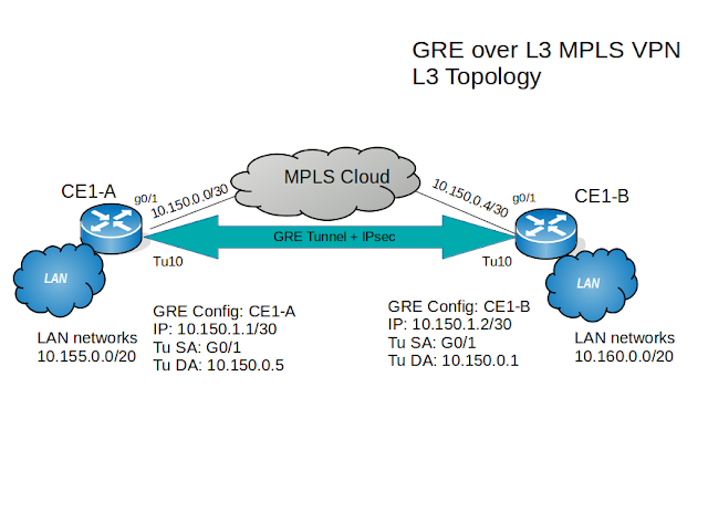
Topology:
Download Lab: EVE-NG | GNS3
Scenario:
Very small project at the client's location, customer's network technicians had GRE tunnel configured, now you need to bring your extended knowledge to perform the implementation of the IPsec, OSPF routing protocol, and direct the financial department's confidential traffic over the encrypted channel. Only financial department LAN networks and the GRE's subnet should participate in the OSPF routing, the rest of the traffic should go over L3 MPLS VPN using existing configuration.
Lab tasks:
1. Configure IPsec and verify its proper operation over the GRE tunnel.
2. Install new LAN networks at the CE1-A and CE1-B routers.
3. Configure the OSPF routing protocol with authentication enabled.
4. Verify LAN-to-LAN connectivity between financial departments' networks.
Lab procedure:
Task1: Configure IPsec and verify its proper operation over the GRE tunnel on router CE1-A and CE1-B.
Step1. Configure IPsec policy:
CE1-A(config)#crypto isakmp policy 5
CE1-A(config-isakmp)#hash sha
CE1-A(config-isakmp)#authentication pre-share
CE1-A(config-isakmp)#group 24
CE1-A(config-isakmp)#lifetime 86400
CE1-A(config-isakmp)#encryption aes 256
CE1-A(config-isakmp)#exit
CE1-A(config)#
Step2. Configure IPsec key for any peer address:
CE1-A(config)#crypto isakmp key mpls-vpn address 0.0.0.0
Step3. Configure IPsec transform-set:
CE1-A(config)#crypto ipsec transform-set SECURE_MPLS_VPN esp-aes 256 esp-sha-hmac
CE1-A(cfg-crypto-trans)#mode tunnel
Step4. Configure IPsec profile:
CE1-A(config)#crypto ipsec profile MPLS_VPN
CE1-A(ipsec-profile)#set transform-set SECURE_MPLS_VPN
CE1-A(ipsec-profile)#exit
Step5. Apply the IPsec profile to the GRE tunnel 10 interface:
CE1-A(config)#interface tunnel 10
CE1-A(config-if)#tunnel protection ipsec profile MPLS_VPN
Step6. Repeat mirror configuration on the other end of the tunnel.
Step7. Verify that traffic is flowing over GRE tunnel encrypted:
CE1-A#ping 10.150.1.2 source tunnel 10
Type escape sequence to abort.
Sending 5, 100-byte ICMP Echos to 10.150.1.2, timeout is 2 seconds:
Packet sent with a source address of 10.150.1.1
!!!!!
Success rate is 100 percent (5/5), round-trip min/avg/max = 8/8/11 ms
CE1-A#
CE1-A#show crypto ipsec sa
interface: Tunnel10
Crypto map tag: Tunnel10-head-0, local addr 10.150.0.1
protected vrf: (none)
local ident (addr/mask/prot/port): (10.150.0.1/255.255.255.255/47/0)
remote ident (addr/mask/prot/port): (10.150.0.5/255.255.255.255/47/0)
current_peer 10.150.0.5 port 500
PERMIT, flags={origin_is_acl,}
#pkts encaps: 5, #pkts encrypt: 5, #pkts digest: 5
#pkts decaps: 5, #pkts decrypt: 5, #pkts verify: 5
#pkts compressed: 0, #pkts decompressed: 0
#pkts not compressed: 0, #pkts compr. failed: 0
#pkts not decompressed: 0, #pkts decompress failed: 0
#send errors 0, #recv errors 0
local crypto endpt.: 10.150.0.1, remote crypto endpt.: 10.150.0.5
plaintext mtu 1438, path mtu 1500, ip mtu 1500, ip mtu idb GigabitEthernet0/1
current outbound spi: 0xF8CA8C26(4174023718)
PFS (Y/N): N, DH group: none
inbound esp sas:
spi: 0xD31538DB(3541383387)
--More--
Task2: Install new LAN networks at the CE1-A and CE1-B routers.
Step1: Using loopback 172 interface simulate the LAN network on the router CE1-A:
CE1-A(config)#interface loopback 172
CE1-A(config-if)#ip address 172.16.0.1 255.255.255.0
CE1-A(config-if)#ip ospf network point-to-point
CE1-A(config-if)#exit
Step2: Using loopback 172 interface simulate the LAN network on the router CE1-B:
CE1-B(config)#interface loopback 172
CE1-B(config-if)#ip address 172.16.16.1 255.255.255.0
CE1-B(config-if)#ip ospf network point-to-point
CE1-B(config-if)#exit
Task3: Configure the OSPF routing protocol with authentication enabled.
Step1. Configure OSPF protocol on the router CE1-A:
CE1-A(config)#router ospf 10
CE1-A(config-router)#router-id 1.1.1.1
CE1-A(config-router)#network 10.150.1.0 0.0.0.3 area 0
CE1-A(config-router)#network 172.16.0.0 0.0.0.255 area 0
CE1-A(config-router)#passive-interface lo0
CE1-A(config-router)#passive-interface lo172
CE1-A(config-router)#exit
Step2. Configure OSPF protocol on the router CE1-B:
CE1-B(config)#router ospf 10
CE1-B(config-router)#router-id 2.2.2.2
CE1-B(config-router)#network 10.150.1.0 0.0.0.3 area 0
CE1-B(config-router)#network 172.16.16.0 0.0.0.255 area 0
CE1-B(config-router)#passive-interface lo0
CE1-B(config-router)#passive-interface lo172
CE1-B(config-router)#exit
Step3. Enable OSPF authentication:
CE1-A(config)#interface tunnel 10
CE1-A(config-if)#ip ospf authentication message-digest
CE1-A(config-if)#ip ospf message-digest-key 1 md5 mpls-vpn
CE1-B(config)#interface tunnel 10
CE1-B(config-if)#ip ospf authentication message-digest
CE1-B(config-if)#ip ospf message-digest-key 1 md5 mpls-vpn
Step4: Verify OSPF implementation, use applicable show commands.
Task4: Verify LAN-to-LAN connectivity between financial departments' networks.
CE1-A#ping 172.16.16.1 source lo172
Type escape sequence to abort.
Sending 5, 100-byte ICMP Echos to 172.16.16.1, timeout is 2 seconds:
Packet sent with a source address of 172.16.0.1
!!!!!
Success rate is 100 percent (5/5), round-trip min/avg/max = 8/8/9 ms
CE1-A#
Also, you can run ping with a large number of repeat count on one router then go to the opposite side router and execute the "show crypto ipsec sa" command multiple times to see the encrypted packets count get increased.
Summary:
The interesting concept introduced in this lab, what has been accomplished is that we have one type of VPN solution running on top of the other, GRE+IPsec is the overlay VPN using MPLS based VPN which is the peer-to-peer model, to carry its traffic over. You can learn from this lab that there is complex network virtualization running in this topology and if there would be an issue with connectivity between client's locations you would have to troubleshoot separately each technology but keep in mind that MPLS related complications have to be resolved first because the successful operation of GRE depends on the stability of MPLS based VPN network and its components.
VIRL: IOSv 15.7
EVE-NG: Cisco vIOS Router vios-15.6
GNS3: vios-adventerprisek9-m.vmdk.SPA.156-2.T
Description:
This is extension lab to the previous lab "Troubleshoot the CE-to-CE connectivity problem", after the successful resolution of the issue, the management team decides to offer the ISP a contract, they want the network team at ISP to assist them with a new project involving the implementation of the IPsec over the GRE tunnel, this project includes the installation of the new LAN network for the financial department, confidential IP traffic should flow over the IPsec tunnel. You as an experienced network security engineer will be performing this configuration.
Topology:

Download Lab: EVE-NG | GNS3
Scenario:
Very small project at the client's location, customer's network technicians had GRE tunnel configured, now you need to bring your extended knowledge to perform the implementation of the IPsec, OSPF routing protocol, and direct the financial department's confidential traffic over the encrypted channel. Only financial department LAN networks and the GRE's subnet should participate in the OSPF routing, the rest of the traffic should go over L3 MPLS VPN using existing configuration.
Lab tasks:
1. Configure IPsec and verify its proper operation over the GRE tunnel.
2. Install new LAN networks at the CE1-A and CE1-B routers.
3. Configure the OSPF routing protocol with authentication enabled.
4. Verify LAN-to-LAN connectivity between financial departments' networks.
Lab procedure:
Task1: Configure IPsec and verify its proper operation over the GRE tunnel on router CE1-A and CE1-B.
Step1. Configure IPsec policy:
CE1-A(config)#crypto isakmp policy 5
CE1-A(config-isakmp)#hash sha
CE1-A(config-isakmp)#authentication pre-share
CE1-A(config-isakmp)#group 24
CE1-A(config-isakmp)#lifetime 86400
CE1-A(config-isakmp)#encryption aes 256
CE1-A(config-isakmp)#exit
CE1-A(config)#
Step2. Configure IPsec key for any peer address:
CE1-A(config)#crypto isakmp key mpls-vpn address 0.0.0.0
Step3. Configure IPsec transform-set:
CE1-A(config)#crypto ipsec transform-set SECURE_MPLS_VPN esp-aes 256 esp-sha-hmac
CE1-A(cfg-crypto-trans)#mode tunnel
Step4. Configure IPsec profile:
CE1-A(config)#crypto ipsec profile MPLS_VPN
CE1-A(ipsec-profile)#set transform-set SECURE_MPLS_VPN
CE1-A(ipsec-profile)#exit
Step5. Apply the IPsec profile to the GRE tunnel 10 interface:
CE1-A(config)#interface tunnel 10
CE1-A(config-if)#tunnel protection ipsec profile MPLS_VPN
Step6. Repeat mirror configuration on the other end of the tunnel.
Step7. Verify that traffic is flowing over GRE tunnel encrypted:
CE1-A#ping 10.150.1.2 source tunnel 10
Type escape sequence to abort.
Sending 5, 100-byte ICMP Echos to 10.150.1.2, timeout is 2 seconds:
Packet sent with a source address of 10.150.1.1
!!!!!
Success rate is 100 percent (5/5), round-trip min/avg/max = 8/8/11 ms
CE1-A#
CE1-A#show crypto ipsec sa
interface: Tunnel10
Crypto map tag: Tunnel10-head-0, local addr 10.150.0.1
protected vrf: (none)
local ident (addr/mask/prot/port): (10.150.0.1/255.255.255.255/47/0)
remote ident (addr/mask/prot/port): (10.150.0.5/255.255.255.255/47/0)
current_peer 10.150.0.5 port 500
PERMIT, flags={origin_is_acl,}
#pkts encaps: 5, #pkts encrypt: 5, #pkts digest: 5
#pkts decaps: 5, #pkts decrypt: 5, #pkts verify: 5
#pkts compressed: 0, #pkts decompressed: 0
#pkts not compressed: 0, #pkts compr. failed: 0
#pkts not decompressed: 0, #pkts decompress failed: 0
#send errors 0, #recv errors 0
local crypto endpt.: 10.150.0.1, remote crypto endpt.: 10.150.0.5
plaintext mtu 1438, path mtu 1500, ip mtu 1500, ip mtu idb GigabitEthernet0/1
current outbound spi: 0xF8CA8C26(4174023718)
PFS (Y/N): N, DH group: none
inbound esp sas:
spi: 0xD31538DB(3541383387)
--More--
Task2: Install new LAN networks at the CE1-A and CE1-B routers.
Step1: Using loopback 172 interface simulate the LAN network on the router CE1-A:
CE1-A(config)#interface loopback 172
CE1-A(config-if)#ip address 172.16.0.1 255.255.255.0
CE1-A(config-if)#ip ospf network point-to-point
CE1-A(config-if)#exit
Step2: Using loopback 172 interface simulate the LAN network on the router CE1-B:
CE1-B(config)#interface loopback 172
CE1-B(config-if)#ip address 172.16.16.1 255.255.255.0
CE1-B(config-if)#ip ospf network point-to-point
CE1-B(config-if)#exit
Task3: Configure the OSPF routing protocol with authentication enabled.
Step1. Configure OSPF protocol on the router CE1-A:
CE1-A(config)#router ospf 10
CE1-A(config-router)#router-id 1.1.1.1
CE1-A(config-router)#network 10.150.1.0 0.0.0.3 area 0
CE1-A(config-router)#network 172.16.0.0 0.0.0.255 area 0
CE1-A(config-router)#passive-interface lo0
CE1-A(config-router)#passive-interface lo172
CE1-A(config-router)#exit
Step2. Configure OSPF protocol on the router CE1-B:
CE1-B(config)#router ospf 10
CE1-B(config-router)#router-id 2.2.2.2
CE1-B(config-router)#network 10.150.1.0 0.0.0.3 area 0
CE1-B(config-router)#network 172.16.16.0 0.0.0.255 area 0
CE1-B(config-router)#passive-interface lo0
CE1-B(config-router)#passive-interface lo172
CE1-B(config-router)#exit
Step3. Enable OSPF authentication:
CE1-A(config)#interface tunnel 10
CE1-A(config-if)#ip ospf authentication message-digest
CE1-A(config-if)#ip ospf message-digest-key 1 md5 mpls-vpn
CE1-B(config)#interface tunnel 10
CE1-B(config-if)#ip ospf authentication message-digest
CE1-B(config-if)#ip ospf message-digest-key 1 md5 mpls-vpn
Step4: Verify OSPF implementation, use applicable show commands.
Task4: Verify LAN-to-LAN connectivity between financial departments' networks.
CE1-A#ping 172.16.16.1 source lo172
Type escape sequence to abort.
Sending 5, 100-byte ICMP Echos to 172.16.16.1, timeout is 2 seconds:
Packet sent with a source address of 172.16.0.1
!!!!!
Success rate is 100 percent (5/5), round-trip min/avg/max = 8/8/9 ms
CE1-A#
Also, you can run ping with a large number of repeat count on one router then go to the opposite side router and execute the "show crypto ipsec sa" command multiple times to see the encrypted packets count get increased.
Summary:
The interesting concept introduced in this lab, what has been accomplished is that we have one type of VPN solution running on top of the other, GRE+IPsec is the overlay VPN using MPLS based VPN which is the peer-to-peer model, to carry its traffic over. You can learn from this lab that there is complex network virtualization running in this topology and if there would be an issue with connectivity between client's locations you would have to troubleshoot separately each technology but keep in mind that MPLS related complications have to be resolved first because the successful operation of GRE depends on the stability of MPLS based VPN network and its components.

Comments
Post a Comment