MPLS Lab 013 OSPF Backdoor Link between CE nodes
Image requirements:
VIRL: IOSv 15.7
EVE-NG: Cisco vIOS Router vios-15.6
GNS3: vios-adventerprisek9-m.vmdk.SPA.156-2.T
Description:
Investigate why OSPF protocol chooses routes over slow backdoor links instead of the faster path via MPLS cloud. The second connection between CE routers has been added to the topology, now customer sites able to communicate over two paths but the second path should be used only as a backup path when there are problems with L3 MPLS VPN connectivity.
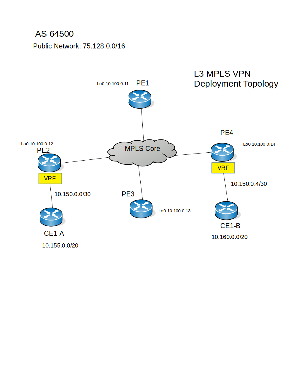
Topology:

Download Lab: EVE-NG | GNS3
Scenario:
In this lab, L3 MPLS VPN has been configured and customer sites able to reach each other LAN networks, OSPF is PE-CE routing choice, and currently, the CE routers using the path over MPLS cloud, the backdoor connection is configured and in the operational state but traffic is not flowing yet via this path. First, you will determine what type of routes are being learned at the CE node via OSPF then you will enable OSPF protocol on the backdoor interfaces and observe what has changed after OSPF neighborship came up over MetroE connection.
Lab tasks:
1. Verify the current OSPF operation on the CE routers, determine how OSPF prefixes have been learned.
2. Configure OSPF over the MetroE network.
3. Observe what has changed after the OSPF protocol has been enabled on the interfaces connected to the MetroE provider.
Lab procedure:
Task1: Verify the current OSPF operation on the CE routers, determine how OSPF prefixes have been learned.
Step1. Access the CLI of CE1-A router in the topology, then use the "show ip route ospf" command to see what prefixes have been learned:
CE1-A#show ip route ospf
Gateway of last resort is not set
10.0.0.0/8 is variably subnetted, 37 subnets, 4 masks
O IA 10.150.0.4/30 [110/2] via 10.150.0.2, 00:51:41, GigabitEthernet0/1
O IA 10.150.0.8/30 [110/2] via 10.150.0.2, 00:51:41, GigabitEthernet0/1
O IA 10.160.0.0/24 [110/3] via 10.150.0.2, 00:51:41, GigabitEthernet0/1
O IA 10.160.1.0/24 [110/3] via 10.150.0.2, 00:51:41, GigabitEthernet0/1
O IA 10.160.2.0/24 [110/3] via 10.150.0.2, 00:51:41, GigabitEthernet0/1
O IA 10.160.3.0/24 [110/3] via 10.150.0.2, 00:51:41, GigabitEthernet0/1
O IA 10.160.4.0/24 [110/3] via 10.150.0.2, 00:51:41, GigabitEthernet0/1
O IA 10.160.5.0/24 [110/3] via 10.150.0.2, 00:51:41, GigabitEthernet0/1
O IA 10.160.6.0/24 [110/3] via 10.150.0.2, 00:51:41, GigabitEthernet0/1
O IA 10.160.7.0/24 [110/3] via 10.150.0.2, 00:51:41, GigabitEthernet0/1
O IA 10.165.0.0/24 [110/3] via 10.150.0.2, 00:51:41, GigabitEthernet0/1
O IA 10.165.1.0/24 [110/3] via 10.150.0.2, 00:51:41, GigabitEthernet0/1
O IA 10.165.3.0/24 [110/3] via 10.150.0.2, 00:51:41, GigabitEthernet0/1
O IA 10.165.4.0/24 [110/3] via 10.150.0.2, 00:51:41, GigabitEthernet0/1
O IA 10.165.5.0/24 [110/3] via 10.150.0.2, 00:51:41, GigabitEthernet0/1
O IA 10.165.6.0/24 [110/3] via 10.150.0.2, 00:51:41, GigabitEthernet0/1
O IA 10.165.7.0/24 [110/3] via 10.150.0.2, 00:51:41, GigabitEthernet0/1
From the output you can see that there are prefixes have been learned, they belong to the CE1-B and CE1-C routers, to reach these subnets router CE1-A uses as the next-hop IP address of PE2 router and the exit interface G0/1, and most important information for this lab is the type of OSPF routes, which is inter-area type.
Step2: Repeat step1 on the CE1-B and CE1-C routers.
Task2: Configure OSPF over the MetroE network.
Step1. Verify the running-config to determine how OSPF protocol currently configured on all three CE routers:
CE1-A#show running-config | section router ospf
router ospf 10
network 10.150.0.0 0.0.0.3 area 0
network 10.155.0.0 0.0.7.255 area 0
CE1-C#show running-config | section router ospf
router ospf 10
network 10.150.0.8 0.0.0.3 area 0
network 10.165.0.0 0.0.7.255 area 0
CE1-B#show running-config | section router ospf
router ospf 10
network 10.150.0.4 0.0.0.3 area 0
network 10.160.0.0 0.0.7.255 area 0
Step2. Check the configuration of the backdoor interfaces and their proper operation:
CE1-A#show ip interface brief
Interface IP-Address OK? Method Status Protocol
GigabitEthernet0/0 10.255.2.212 YES NVRAM administratively down down
GigabitEthernet0/1 10.150.0.1 YES NVRAM up up
GigabitEthernet0/2 10.150.0.17 YES NVRAM up up
GigabitEthernet0/3 unassigned YES unset administratively down down
Loopback0 10.155.0.1 YES NVRAM up up
Loopback1 10.155.1.1 YES NVRAM up up
Loopback2 10.155.2.1 YES NVRAM up up
Loopback3 10.155.3.1 YES NVRAM up up
Loopback4 10.155.4.1 YES NVRAM up up
Loopback5 10.155.5.1 YES NVRAM up up
Loopback6 10.155.6.1 YES NVRAM up up
Loopback7 10.155.7.1 YES NVRAM up up
CE1-A#show ip route connected | section 10.150.0.16
C 10.150.0.16/28 is directly connected, GigabitEthernet0/2
CE1-A#ping 10.150.0.18 source g0/2
Type escape sequence to abort.
Sending 5, 100-byte ICMP Echos to 10.150.0.18, timeout is 2 seconds:
Packet sent with a source address of 10.150.0.17
!!!!!
Success rate is 100 percent (5/5), round-trip min/avg/max = 2/2/3 ms
CE1-A#ping 10.150.0.19 source g0/2
Type escape sequence to abort.
Sending 5, 100-byte ICMP Echos to 10.150.0.19, timeout is 2 seconds:
Packet sent with a source address of 10.150.0.17
!!!!!
Success rate is 100 percent (5/5), round-trip min/avg/max = 1/2/3 ms
CE1-A#
Step3. Enable OSPF for the network 10.150.0.16/28 on CE routers:
CE1-A(config)#router ospf 10
CE1-A(config-router)#network 10.150.0.16 0.0.0.15 area 0
CE1-A(config-router)#end
CE1-C(config)#router ospf 10
CE1-C(config-router)#network 10.150.0.16 0.0.0.15 area 0
CE1-C(config-router)#end
CE1-B(config)#router ospf 10
CE1-B(config-router)#network 10.150.0.16 0.0.0.15 area 0
CE1-B(config-router)#end
Step4: Verify the new OSPF neighborships:
CE1-A#show ip ospf neighbor
Neighbor ID Pri State Dead Time Address Interface
10.160.7.1 1 FULL/DROTHER 00:00:34 10.150.0.19 GigabitEthernet0/2
10.165.7.1 1 FULL/BDR 00:00:38 10.150.0.18 GigabitEthernet0/2
10.150.0.2 1 FULL/BDR 00:00:36 10.150.0.2 GigabitEthernet0/1
CE1-A#
Task3: Observe what has changed after the OSPF protocol has been enabled on the interfaces connected to the MetroE provider.
CE1-A#show ip route ospf
Codes: L - local, C - connected, S - static, R - RIP, M - mobile, B - BGP
D - EIGRP, EX - EIGRP external, O - OSPF, IA - OSPF inter area
N1 - OSPF NSSA external type 1, N2 - OSPF NSSA external type 2
E1 - OSPF external type 1, E2 - OSPF external type 2
i - IS-IS, su - IS-IS summary, L1 - IS-IS level-1, L2 - IS-IS level-2
ia - IS-IS inter area, * - candidate default, U - per-user static route
o - ODR, P - periodic downloaded static route, H - NHRP, l - LISP
a - application route
+ - replicated route, % - next hop override, p - overrides from PfR
Gateway of last resort is not set
10.0.0.0/8 is variably subnetted, 37 subnets, 4 masks
O 10.150.0.4/30 [110/2] via 10.150.0.19, 00:05:27, GigabitEthernet0/2
O 10.150.0.8/30 [110/2] via 10.150.0.18, 00:07:50, GigabitEthernet0/2
O 10.160.0.0/24 [110/2] via 10.150.0.19, 00:05:27, GigabitEthernet0/2
O 10.160.1.0/24 [110/2] via 10.150.0.19, 00:05:27, GigabitEthernet0/2
O 10.160.2.0/24 [110/2] via 10.150.0.19, 00:05:27, GigabitEthernet0/2
O 10.160.3.0/24 [110/2] via 10.150.0.19, 00:05:27, GigabitEthernet0/2
O 10.160.4.0/24 [110/2] via 10.150.0.19, 00:05:27, GigabitEthernet0/2
O 10.160.5.0/24 [110/2] via 10.150.0.19, 00:05:27, GigabitEthernet0/2
O 10.160.6.0/24 [110/2] via 10.150.0.19, 00:05:27, GigabitEthernet0/2
O 10.160.7.0/24 [110/2] via 10.150.0.19, 00:05:27, GigabitEthernet0/2
O 10.165.0.0/24 [110/2] via 10.150.0.18, 00:07:50, GigabitEthernet0/2
O 10.165.1.0/24 [110/2] via 10.150.0.18, 00:07:50, GigabitEthernet0/2
O 10.165.3.0/24 [110/2] via 10.150.0.18, 00:07:50, GigabitEthernet0/2
O 10.165.4.0/24 [110/2] via 10.150.0.18, 00:07:50, GigabitEthernet0/2
O 10.165.5.0/24 [110/2] via 10.150.0.18, 00:07:50, GigabitEthernet0/2
O 10.165.6.0/24 [110/2] via 10.150.0.18, 00:07:50, GigabitEthernet0/2
O 10.165.7.0/24 [110/2] via 10.150.0.18, 00:07:50, GigabitEthernet0/2
As you can see that now the OSPF route type has changed to the "intra-area" and as you know from your Cisco studies that OSPF will prefer intra-area routes over inter-area. But we need OSPF to choose the path over MPLS cloud as the main and path over MetroE as the backup.
The solution is to configure the sham-link between PE routers, this type of link is like virtual-link but for MPLS environment, when you establish the sham-link, on both sides of CE routers the separated backbone areas merged into one and the prefixes changed to intra-area type, that will allow the CE routers to load balance between two paths or prefer one path over another.
Summary:
This lab shows you what happened to the OSPF routes coming from the peer over the MPLS cloud when the backdoor path introduced into the topology, in the next lab the configuration of sham-link will be performed.
VIRL: IOSv 15.7
EVE-NG: Cisco vIOS Router vios-15.6
GNS3: vios-adventerprisek9-m.vmdk.SPA.156-2.T
Description:
Investigate why OSPF protocol chooses routes over slow backdoor links instead of the faster path via MPLS cloud. The second connection between CE routers has been added to the topology, now customer sites able to communicate over two paths but the second path should be used only as a backup path when there are problems with L3 MPLS VPN connectivity.
Topology:
Download Lab: EVE-NG | GNS3
Scenario:
In this lab, L3 MPLS VPN has been configured and customer sites able to reach each other LAN networks, OSPF is PE-CE routing choice, and currently, the CE routers using the path over MPLS cloud, the backdoor connection is configured and in the operational state but traffic is not flowing yet via this path. First, you will determine what type of routes are being learned at the CE node via OSPF then you will enable OSPF protocol on the backdoor interfaces and observe what has changed after OSPF neighborship came up over MetroE connection.
Lab tasks:
1. Verify the current OSPF operation on the CE routers, determine how OSPF prefixes have been learned.
2. Configure OSPF over the MetroE network.
3. Observe what has changed after the OSPF protocol has been enabled on the interfaces connected to the MetroE provider.
Lab procedure:
Task1: Verify the current OSPF operation on the CE routers, determine how OSPF prefixes have been learned.
Step1. Access the CLI of CE1-A router in the topology, then use the "show ip route ospf" command to see what prefixes have been learned:
CE1-A#show ip route ospf
Gateway of last resort is not set
10.0.0.0/8 is variably subnetted, 37 subnets, 4 masks
O IA 10.150.0.4/30 [110/2] via 10.150.0.2, 00:51:41, GigabitEthernet0/1
O IA 10.150.0.8/30 [110/2] via 10.150.0.2, 00:51:41, GigabitEthernet0/1
O IA 10.160.0.0/24 [110/3] via 10.150.0.2, 00:51:41, GigabitEthernet0/1
O IA 10.160.1.0/24 [110/3] via 10.150.0.2, 00:51:41, GigabitEthernet0/1
O IA 10.160.2.0/24 [110/3] via 10.150.0.2, 00:51:41, GigabitEthernet0/1
O IA 10.160.3.0/24 [110/3] via 10.150.0.2, 00:51:41, GigabitEthernet0/1
O IA 10.160.4.0/24 [110/3] via 10.150.0.2, 00:51:41, GigabitEthernet0/1
O IA 10.160.5.0/24 [110/3] via 10.150.0.2, 00:51:41, GigabitEthernet0/1
O IA 10.160.6.0/24 [110/3] via 10.150.0.2, 00:51:41, GigabitEthernet0/1
O IA 10.160.7.0/24 [110/3] via 10.150.0.2, 00:51:41, GigabitEthernet0/1
O IA 10.165.0.0/24 [110/3] via 10.150.0.2, 00:51:41, GigabitEthernet0/1
O IA 10.165.1.0/24 [110/3] via 10.150.0.2, 00:51:41, GigabitEthernet0/1
O IA 10.165.3.0/24 [110/3] via 10.150.0.2, 00:51:41, GigabitEthernet0/1
O IA 10.165.4.0/24 [110/3] via 10.150.0.2, 00:51:41, GigabitEthernet0/1
O IA 10.165.5.0/24 [110/3] via 10.150.0.2, 00:51:41, GigabitEthernet0/1
O IA 10.165.6.0/24 [110/3] via 10.150.0.2, 00:51:41, GigabitEthernet0/1
O IA 10.165.7.0/24 [110/3] via 10.150.0.2, 00:51:41, GigabitEthernet0/1
From the output you can see that there are prefixes have been learned, they belong to the CE1-B and CE1-C routers, to reach these subnets router CE1-A uses as the next-hop IP address of PE2 router and the exit interface G0/1, and most important information for this lab is the type of OSPF routes, which is inter-area type.
Step2: Repeat step1 on the CE1-B and CE1-C routers.
Task2: Configure OSPF over the MetroE network.
Step1. Verify the running-config to determine how OSPF protocol currently configured on all three CE routers:
CE1-A#show running-config | section router ospf
router ospf 10
network 10.150.0.0 0.0.0.3 area 0
network 10.155.0.0 0.0.7.255 area 0
CE1-C#show running-config | section router ospf
router ospf 10
network 10.150.0.8 0.0.0.3 area 0
network 10.165.0.0 0.0.7.255 area 0
CE1-B#show running-config | section router ospf
router ospf 10
network 10.150.0.4 0.0.0.3 area 0
network 10.160.0.0 0.0.7.255 area 0
Step2. Check the configuration of the backdoor interfaces and their proper operation:
CE1-A#show ip interface brief
Interface IP-Address OK? Method Status Protocol
GigabitEthernet0/0 10.255.2.212 YES NVRAM administratively down down
GigabitEthernet0/1 10.150.0.1 YES NVRAM up up
GigabitEthernet0/2 10.150.0.17 YES NVRAM up up
GigabitEthernet0/3 unassigned YES unset administratively down down
Loopback0 10.155.0.1 YES NVRAM up up
Loopback1 10.155.1.1 YES NVRAM up up
Loopback2 10.155.2.1 YES NVRAM up up
Loopback3 10.155.3.1 YES NVRAM up up
Loopback4 10.155.4.1 YES NVRAM up up
Loopback5 10.155.5.1 YES NVRAM up up
Loopback6 10.155.6.1 YES NVRAM up up
Loopback7 10.155.7.1 YES NVRAM up up
CE1-A#show ip route connected | section 10.150.0.16
C 10.150.0.16/28 is directly connected, GigabitEthernet0/2
CE1-A#ping 10.150.0.18 source g0/2
Type escape sequence to abort.
Sending 5, 100-byte ICMP Echos to 10.150.0.18, timeout is 2 seconds:
Packet sent with a source address of 10.150.0.17
!!!!!
Success rate is 100 percent (5/5), round-trip min/avg/max = 2/2/3 ms
CE1-A#ping 10.150.0.19 source g0/2
Type escape sequence to abort.
Sending 5, 100-byte ICMP Echos to 10.150.0.19, timeout is 2 seconds:
Packet sent with a source address of 10.150.0.17
!!!!!
Success rate is 100 percent (5/5), round-trip min/avg/max = 1/2/3 ms
CE1-A#
Step3. Enable OSPF for the network 10.150.0.16/28 on CE routers:
CE1-A(config)#router ospf 10
CE1-A(config-router)#network 10.150.0.16 0.0.0.15 area 0
CE1-A(config-router)#end
CE1-C(config)#router ospf 10
CE1-C(config-router)#network 10.150.0.16 0.0.0.15 area 0
CE1-C(config-router)#end
CE1-B(config)#router ospf 10
CE1-B(config-router)#network 10.150.0.16 0.0.0.15 area 0
CE1-B(config-router)#end
Step4: Verify the new OSPF neighborships:
CE1-A#show ip ospf neighbor
Neighbor ID Pri State Dead Time Address Interface
10.160.7.1 1 FULL/DROTHER 00:00:34 10.150.0.19 GigabitEthernet0/2
10.165.7.1 1 FULL/BDR 00:00:38 10.150.0.18 GigabitEthernet0/2
10.150.0.2 1 FULL/BDR 00:00:36 10.150.0.2 GigabitEthernet0/1
CE1-A#
Task3: Observe what has changed after the OSPF protocol has been enabled on the interfaces connected to the MetroE provider.
CE1-A#show ip route ospf
Codes: L - local, C - connected, S - static, R - RIP, M - mobile, B - BGP
D - EIGRP, EX - EIGRP external, O - OSPF, IA - OSPF inter area
N1 - OSPF NSSA external type 1, N2 - OSPF NSSA external type 2
E1 - OSPF external type 1, E2 - OSPF external type 2
i - IS-IS, su - IS-IS summary, L1 - IS-IS level-1, L2 - IS-IS level-2
ia - IS-IS inter area, * - candidate default, U - per-user static route
o - ODR, P - periodic downloaded static route, H - NHRP, l - LISP
a - application route
+ - replicated route, % - next hop override, p - overrides from PfR
Gateway of last resort is not set
10.0.0.0/8 is variably subnetted, 37 subnets, 4 masks
O 10.150.0.4/30 [110/2] via 10.150.0.19, 00:05:27, GigabitEthernet0/2
O 10.150.0.8/30 [110/2] via 10.150.0.18, 00:07:50, GigabitEthernet0/2
O 10.160.0.0/24 [110/2] via 10.150.0.19, 00:05:27, GigabitEthernet0/2
O 10.160.1.0/24 [110/2] via 10.150.0.19, 00:05:27, GigabitEthernet0/2
O 10.160.2.0/24 [110/2] via 10.150.0.19, 00:05:27, GigabitEthernet0/2
O 10.160.3.0/24 [110/2] via 10.150.0.19, 00:05:27, GigabitEthernet0/2
O 10.160.4.0/24 [110/2] via 10.150.0.19, 00:05:27, GigabitEthernet0/2
O 10.160.5.0/24 [110/2] via 10.150.0.19, 00:05:27, GigabitEthernet0/2
O 10.160.6.0/24 [110/2] via 10.150.0.19, 00:05:27, GigabitEthernet0/2
O 10.160.7.0/24 [110/2] via 10.150.0.19, 00:05:27, GigabitEthernet0/2
O 10.165.0.0/24 [110/2] via 10.150.0.18, 00:07:50, GigabitEthernet0/2
O 10.165.1.0/24 [110/2] via 10.150.0.18, 00:07:50, GigabitEthernet0/2
O 10.165.3.0/24 [110/2] via 10.150.0.18, 00:07:50, GigabitEthernet0/2
O 10.165.4.0/24 [110/2] via 10.150.0.18, 00:07:50, GigabitEthernet0/2
O 10.165.5.0/24 [110/2] via 10.150.0.18, 00:07:50, GigabitEthernet0/2
O 10.165.6.0/24 [110/2] via 10.150.0.18, 00:07:50, GigabitEthernet0/2
O 10.165.7.0/24 [110/2] via 10.150.0.18, 00:07:50, GigabitEthernet0/2
As you can see that now the OSPF route type has changed to the "intra-area" and as you know from your Cisco studies that OSPF will prefer intra-area routes over inter-area. But we need OSPF to choose the path over MPLS cloud as the main and path over MetroE as the backup.
The solution is to configure the sham-link between PE routers, this type of link is like virtual-link but for MPLS environment, when you establish the sham-link, on both sides of CE routers the separated backbone areas merged into one and the prefixes changed to intra-area type, that will allow the CE routers to load balance between two paths or prefer one path over another.
Summary:
This lab shows you what happened to the OSPF routes coming from the peer over the MPLS cloud when the backdoor path introduced into the topology, in the next lab the configuration of sham-link will be performed.

Comments
Post a Comment