DMVPN Lab 1 Configuration
Previous Next
Download Lab: EVE-NG
Image needed: Cisco IOSv
Description:
Four branch routers need to be connected to the corporate datacenter, configure entire infrastructure for this topology including basic configurations for the ISP router then IPv4 connections between HQ office and Branches are established, setup DMVPN communication. Directions to this lab are included within, check "Labs Task(s) for more details after you open .unl file.
Topology:
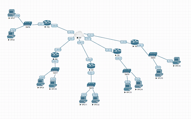
Step1: Configure LAN interface G0/1 on the HQ router with the first IP address from 172.16.0.0/24 subnet.
Step2: Configure LAN interface G0/1 on the R3 router with the first IP address from 192.168.3.0/24 network.
Step3: Configure LAN interface G0/1 on the R4 router with the first IP address from 192.168.4.0/24 network.
Step4: Configure LAN interface G0/1 on the R5 router with the first IP address from 192.168.5.0/24 network.
Step5: Configure LAN interface G0/1 on the R6 router with the first IP address from 192.168.6.0/24 network.
Step6: Save configurations on all affected routers.
Task4: DMVPN hub
Task6: RIPv2
Step1: Configure to run Routing Information Protocol Version 2 between hub and spokes in the DMVPN topology.
Step2: Verify the routing table.
Step3: Manually assign IP addresses to VPCs according to the topology. Host number 10 will be allocated for the first VPC and 20 for the second.
Step4: Verify connectivity between subnets.
Step5: Save configurations.
Command reference:
R6(config)# router rip
R6(config-router)# version 2
R6(config-router)# no auto-summary
R6(config-router)# passive-interface default
R6(config-router)# no passive-interface Tunnel1
R6(config-router)# network 10.0.0.0
R6(config-router)# 192.168.6.0
Verify RIP:
R6# show ip protocol
R6# show ip route rip
Task7: Troubleshooting
Ticket:
After the implementation of configurations from previous tasks, users in spokes LANs still unable to access each other, the only connectivity over DMVPN is to the Hub's LAN subnet 172.16.0.0/24.
Step1: Verify IP routing table on the spoke routers (R3, R4, R5, R6)
Step2: Define the problem. ( RIP's loop prevention mechanism causing HQ router not to advertise routes back to spokes.)
Step3: Fix the problem. ( Disable this technology on the HQ router's tunnel0 interface)
Step4: Verify connectivity and routing table again.
Step5: Save configuration on the HQ router.
Download Lab: EVE-NG
Image needed: Cisco IOSv
Description:
Four branch routers need to be connected to the corporate datacenter, configure entire infrastructure for this topology including basic configurations for the ISP router then IPv4 connections between HQ office and Branches are established, setup DMVPN communication. Directions to this lab are included within, check "Labs Task(s) for more details after you open .unl file.
Topology:

Task1:
Step1: Configure the ISP router. Give a hostname.
Step2: Interface G0/0, Assign first IP address from 50.0.0.0/30 subnet and write a description
Step3: Interface G0/1, Assign first IP address from 60.0.0.0/30 subnet and write a description
Step4: Interface G0/2, Assign first IP address from 70.0.0.0/30 subnet and write a description
Step5: Interface G0/3, Assign first IP address from 80.0.0.0/30 subnet and write a description
Step6: Interface G0/4, Assign first IP address from 90.0.0.0/30 subnet and write a description
Step7: Verify briefly the state of IP configurations on the ISP router.
Step8: Check IP routing table for any mistakes or mistypes
Step9: Save applied configurations.
Task2:
Step1: Configure IP settings on the hub HQ router and its spoke
routers R3, R4, R5, and R6, according to the ISP's IP design performed
in the previous task.
Step2: Create a Static default route on each router attached to the ISP router via a point-to-point link, using the next-hop IP address.
Step3: Verify IP connectivity from HQ router to each of its spoke routers, using its G0/0 interface as the source for ICMP requests.
Step4: If ping succeeded from the previous step then save the configuration and proceed to the next task otherwise troubleshoot the IP connectivity!
Task3:
Step2: Configure LAN interface G0/1 on the R3 router with the first IP address from 192.168.3.0/24 network.
Step3: Configure LAN interface G0/1 on the R4 router with the first IP address from 192.168.4.0/24 network.
Step4: Configure LAN interface G0/1 on the R5 router with the first IP address from 192.168.5.0/24 network.
Step5: Configure LAN interface G0/1 on the R6 router with the first IP address from 192.168.6.0/24 network.
Step6: Save configurations on all affected routers.
Task4: DMVPN hub
Step1: Enter interface tunnel 0 configuration mode on the HQ router.
Step2: Configure DMVPN parameters. IP subnet will be 10.0.0.0/24, the first IP assigned to the hub.
Step3: Verify interface tunnel 0 configurations.
Step4: Save configurations.
Command reference for DMVPN hub:
R1(config)# interface tunnel 0
R1(config-if)# tunnel source S0/0
R1(config-if)# tunnel mode gre multipoint
R1(Config-if)# tunnel key 1234
R1(config-if)# ip nhrp network-id 1
R1(Config-if)# ip nhrp authentication ciscoccnp
R1(config-if)# ip nhrp map multicast dynamic
R1(Config-if)# ip address 192.168.1.1 255.255.255.0
R1(config-if)# tunnel path-mtu-discovery (or) ip mtu 1400
R1(config-if)# ip tcp adjust-mss 1360
R1(config-if)# exit
Verify DMVPN.
R1#show run interface tunnel0
R1# show ip interface tunnel0
R1# show ip interface brief
Task5: DMVPN Spoke
Step1: Configure DMVPN on the spoke routers R3, R4, R5, R6, using interface tunnel 1.
Step2: Verify DMVPN states of tunnels.
Step3: Save configurations.
Command reference.
R2(config)# interface tunnel 1
R2(config-if)# tunnel source S0/0
R2(config-if)# tunnel mode gre multipoint
R2(config-if)# tunnel key 1234
R2(config-if)# ip nhrp network-id 1
R2(config-if)# ip nhrp authentication ciscpccnp
R2(config-if)# ip nhrp map multicast dynamic
R2(config-if)# ip nhrp nhs 192.168.1.1
R2(config-if)# ip nhrp map 192.168.1.1 54.10.1.1
R2(config-if)# ip nhrp map multicast 54.10.1.1
R2(config-if)# ip address 192.168.1.2 255.255.255.0
R2(config-if)# ip mtu 1400
R2(config-if)# ip tcp adjust-mss 1360
Verification:
R2# show ip nhrp
R2# show dmvpn
R2# show dmvpn detail
Task6: RIPv2
Step1: Configure to run Routing Information Protocol Version 2 between hub and spokes in the DMVPN topology.
Step2: Verify the routing table.
Step3: Manually assign IP addresses to VPCs according to the topology. Host number 10 will be allocated for the first VPC and 20 for the second.
Step4: Verify connectivity between subnets.
Step5: Save configurations.
Command reference:
R6(config)# router rip
R6(config-router)# version 2
R6(config-router)# no auto-summary
R6(config-router)# passive-interface default
R6(config-router)# no passive-interface Tunnel1
R6(config-router)# network 10.0.0.0
R6(config-router)# 192.168.6.0
Verify RIP:
R6# show ip protocol
R6# show ip route rip
Task7: Troubleshooting
Ticket:
After the implementation of configurations from previous tasks, users in spokes LANs still unable to access each other, the only connectivity over DMVPN is to the Hub's LAN subnet 172.16.0.0/24.
Step1: Verify IP routing table on the spoke routers (R3, R4, R5, R6)
Step2: Define the problem. ( RIP's loop prevention mechanism causing HQ router not to advertise routes back to spokes.)
Step3: Fix the problem. ( Disable this technology on the HQ router's tunnel0 interface)
Step4: Verify connectivity and routing table again.
Step5: Save configuration on the HQ router.

Comments
Post a Comment